ENGINE ASSEMBLY REMOVAL

-
PRECAUTION
Note
After turning the ignition switch off, waiting time may be required before disconnecting the cable from the battery terminal. Therefore, make sure to read the disconnecting the cable from the battery terminal notice before proceeding with work Click here.
-
DISCHARGE FUEL SYSTEM PRESSURE
-
DISCONNECT CABLE FROM NEGATIVE BATTERY TERMINAL
-
REMOVE FRONT WIPER MOTOR AND LINK ASSEMBLY
-
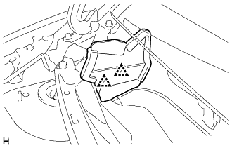
REMOVE FRONT AIR SHUTTER SEAL RH
-
Remove the 2 clips and front air shutter seal RH.
-
-
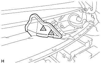
REMOVE FRONT NO. 1 VENTILATOR SEAL
-
Remove the 2 clips and No. 1 front ventilator seal.
-
-
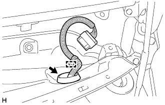
REMOVE COWL TOP PANEL OUTER
-
Disengage the wire harness clamp.
-
Disengage the grommet and separate the wire harness.
-
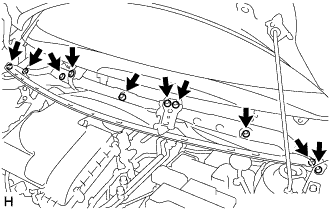
Remove the 10 bolts and cowl top panel outer.
-
-
REMOVE BATTERY
-
Loosen the nut and disconnect the battery positive (+) terminal.
-
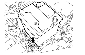
Remove the bolt and the battery clamp.
-
Remove the battery.
-
-
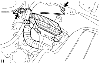
SEPARATE ENGINE ROOM RELAY BLOCK
-
Remove the engine room relay block cover.
-
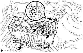
Disconnect the 3 connectors from the engine room relay block.
-
Disengage the 2 claws and separate the wire harness.
-
Remove the 2 bolts.
-
Disengage the 4 wire harness clamps and separate the engine room relay block.
-
-
REMOVE BATTERY CLAMP SUB-ASSEMBLY
-
Remove the 3 bolts and the battery clamp sub-assembly.
-
-
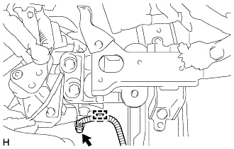
DISCONNECT ENGINE WIRE
-
Disengage the wire harness clamp.
-
Remove the bolt and disconnect the ground wire from the transaxle.
-
Remove the 2 bolts and disconnect the 2 ground wires.
-
Disengage the wire harness clamp.
-
Slide the levers to disengage the locks, and separate the 2 connectors from the ECM.
Text in Illustration 
Slide -
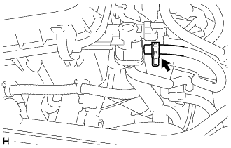
Remove the nut and disconnect the battery terminal B.
-
-
REMOVE AIR CLEANER CAP SUB-ASSEMBLY
-
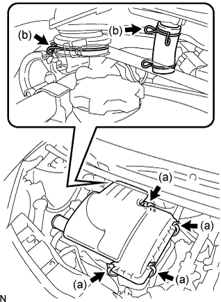
Remove the 4 clamps.
-
Remove the 2 clamps, then remove the air cleaner cap and air cleaner filter element.
-
-
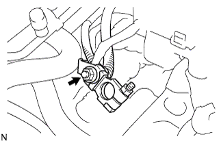
SEPARATE ACCELERATOR CONTROL CABLE ASSEMBLY
-
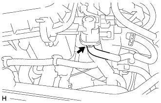
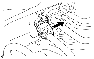
Loosen the nut shown in the illustration, and then disconnect the accelerator control cable.
-
-
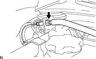
REMOVE NO. 1 FUEL VAPOR FEED HOSE
-
Loosen the hose clip and disconnect the No. 1 fuel vapor feed hose.
-
-
REMOVE NO. 2 FUEL VAPOR FEED HOSE
-
Loosen the hose clip and disconnect the No. 2 fuel vapor feed hose.
-
-
REMOVE FRONT BUMPER COVER
-
REMOVE FAN AND GENERATOR V BELT
-
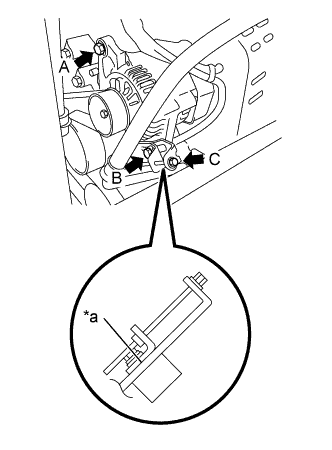
Text in Illustration *a No Measurable Clearance Loosen the A bolt.
-
Loosen the B bolt.
-
Loosely tighten the B bolt until there is no measurable clearance.
-
Loosen the C bolt.
-
Remove the fan and generator V belt.
-
-
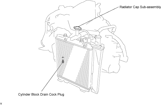
DRAIN ENGINE COOLANT
Note
To avoid the danger of being burned, do not remove the radiator cap sub-assembly while the engine and radiator assembly are still hot. Thermal expansion will cause hot engine coolant and steam to blow out from the radiator assembly.
-
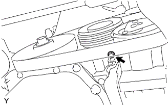
Loosen the cylinder block drain cock plug, then drain the engine coolant.
Tech Tips
The cylinder block drain cock plug is positioned on the bottom edge of the timing chain or belt cover sub-assembly.
-
Remove the radiator cap sub-assembly.
-
Disconnect the radiator outlet hose from the engine side, then drain the engine coolant by bending the hose.
-
-
REMOVE FRONT EXHAUST PIPE ASSEMBLY
-
REMOVE INLET RADIATOR HOSE
-
REMOVE OUTLET RADIATOR HOSE
-
REMOVE RADIATOR ASSEMBLY
-
SEPARATE COMPRESSOR WITH PULLEY ASSEMBLY (w/ Air Conditioning System)
Tech Tips
It is not necessary to completely remove the compressor. With the hoses connected to the compressor, hang the compressor on the vehicle body with a rope.
-
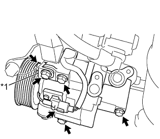
Text in Illustration *1 No. 1 Compressor Stay Disconnect the connector.
-
Remove the bolt, nut and No. 1 compressor stay.
-
Remove the 3 bolts and separate the compressor with pulley assembly.
-
-
DISCONNECT VACUUM HOSE ASSEMBLY
-
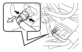
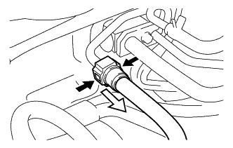
Pinch the retainer as illustrated, then pull out the vacuum hose connector from the pipe.
Text in Illustration 
Pinch Pull
-
-
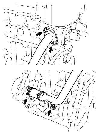
DISCONNECT HEATER WATER HOSE INLET A
-
Loosen the hose clip and disconnect the heater water inlet hose A.
-
-
DISCONNECT HEATER WATER OUTLET HOSE A
Tech Tips
Disconnection procedure for the heater water outlet hose A is the same as for the heater water inlet hose A.
-
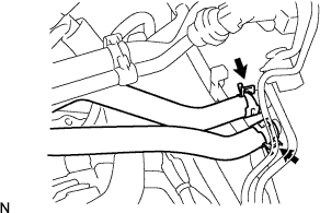
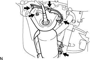
REMOVE FUEL TUBE SUB-ASSEMBLY
-
Remove the fuel pipe clamp.
-
Pinch the retainer as illustrated, then pull out the fuel tube connector from the pipe.
Text in Illustration Pinch Pull Note
-
Remove any dirt and foreign objects on the fuel tube connector before performing this work.
-
Do not allow any scratches or foreign objects on the O-rings of the fuel tube connector, otherwise the pipe may not be sealed properly.
-
Perform this work by hand. Do not use any tools.
-
Do not forcibly bend, twist, or turn the nylon tube.
-
Protect the disconnected part by covering it with a vinyl bag after disconnecting the fuel tube.
-
If the fuel tube connector and pipe are stuck, separate them by pushing and pulling on the connection.
-
-
-
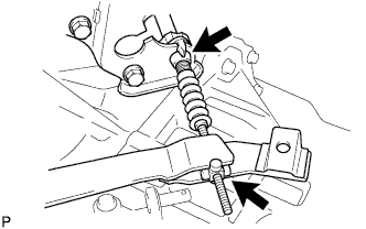
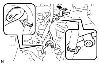
SEPARATE TRANSAXLE CONTROL CABLE ASSEMBLY
-
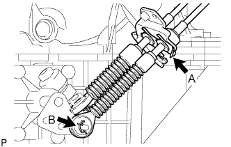
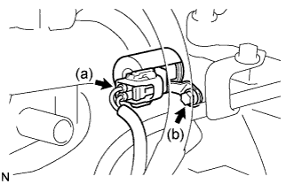
Remove the clip A and clip B, then separate the transmission shift cable from the manual transaxle.
-
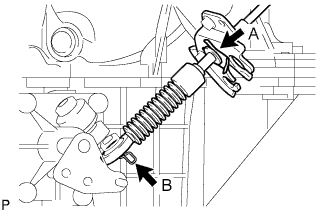
Remove the clip A and clip B, then separate the transmission select cable from the manual transaxle.
-
-
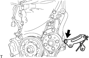
REMOVE CLUTCH RELEASE FORK RETURN TENSION SPRING
-
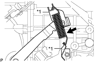
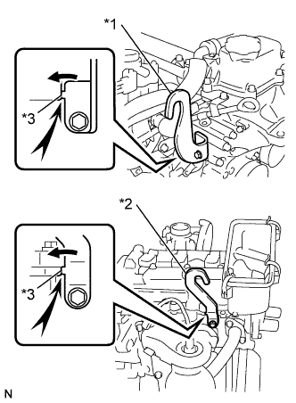
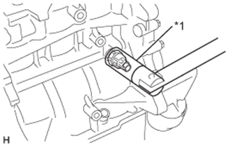
Text in Illustration *1 Spring Hanger Remove the clutch release fork return tension spring from the spring hanger.
Note
-
If there is any rust or deformation in the tension spring, replace it.
-
If there is any damage in the tension spring damper, replace it.
-
-
-
SEPARATE CLUTCH RELEASE CABLE ASSEMBLY
-
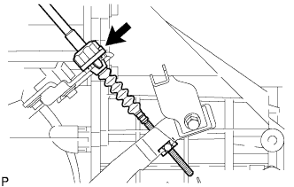
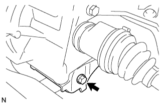
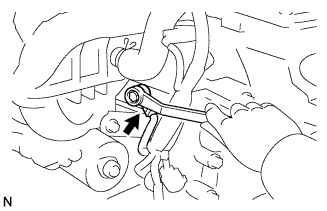
Turn and loosen the clutch release cable adjusting nut.
-
Separate the clutch release cable assembly from the manual transaxle assembly.
-
-
PLACE FRONT WHEELS FACING STRAIGHT A HEAD
-
REMOVE STEERING COLUMN HOLE COVER PLATE
-
Turn back the floor carpet and disengage the 2 claws from the steering column hole cover plate.
-
-
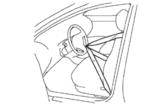
SEPARATE NO. 2 STEERING INTERMEDIATE SHAFT ASSEMBLY
-
Hold the steering wheel assembly with the seat belt in order to prevent rotation and damage to the spiral cable.
-
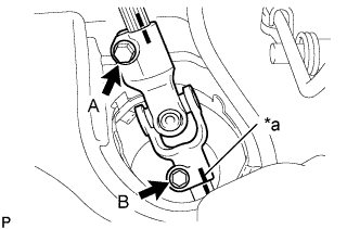
Text in Illustration *a Matchmark Place matchmarks on the No. 2 steering intermediate shaft assembly and the steering gear assembly.
-
Loosen bolt A and remove bolt B to separate the No. 2 steering intermediate shaft assembly.
-
-
SEPARATE NO. 1 STEERING COLUMN HOLE COVER SUB-ASSEMBLY
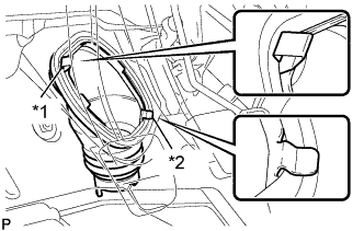
Text in Illustration *1 Clip A *2 Clip B
-
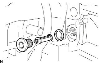
Remove clip A and separate the No. 1 steering column hole cover sub-assembly from the body.
Note
Do not damage clip B.
-
-
DRAIN MANUAL TRANSAXLE OIL
-
Remove the filler plug and gasket.
-
Remove the drain plug and gasket, and then drain the manual transaxle oil.
-
-
REMOVE FRONT DRIVE SHAFT ASSEMBLY
-
REMOVE ENGINE ASSEMBLY WITH TRANSAXLE
-
Set the engine lifter.
-
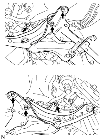
Remove the 4 bolts and nut from the engine mounting insulator RH.
-
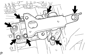
Remove the 7 bolts and engine mounting insulator LH.
-
Remove the 6 bolts, the engine assembly with transaxle and the front suspension crossmember from the vehicle.
-
Text in Illustration *1 Engine Hanger *2 No. 2 Engine Hanger *3 Stopper Install the 2 engine hangers with the 2 bolts.
- Torque:
- 28 N*m { 285 kgf*cm, 21 ft.*lbf }
Tech Tips
Part Name Part No. Engine Hanger 12281-40032 No. 2 Engine Hanger 12282-40010 Bolt 91671-80820 Be sure to hold down on the stopper when installing the engine hanger.
-
Attach the engine sling and hang the engine with the chain block.
-
-
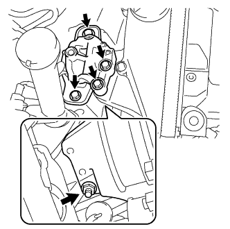
REMOVE FRONT SUSPENSION CROSSMEMBER SUB-ASSEMBLY
-
Remove the bolt and the engine assembly with transaxle from the front suspension crossmember assembly.
-
-
REMOVE STARTER ASSEMBLY
-
Open the terminal cap, remove the nut and disconnect the wire harness from terminal 50.
-
Open the terminal cap, remove the nut and disconnect the wire harness from terminal 30.
-
Remove the bolt, and wire harness clamp.
-
Remove the 2 bolts, and the starter.
-
-
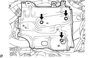
REMOVE FLYWHEEL HOUSING SIDE COVER
-
REMOVE FLYWHEEL HOUSING UNDER COVER
-
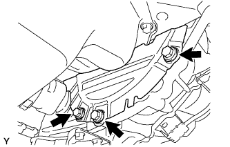
Remove the 3 bolts and the flywheel housing under cover from the manual transaxle assembly.
-
-
REMOVE MANUAL TRANSAXLE ASSEMBLY
-
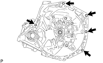
Remove the 5 bolts and the manual transaxle assembly from the engine assembly.
Note
-
To avoid damage to the knock pins, do not pry between the manual transaxle assembly and the engine assembly.
-
To avoid damage to the input shaft, do not forcefully shake the manual transaxle assembly.
-
-
-
REMOVE CLUTCH COVER ASSEMBLY
-
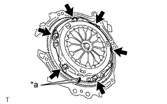
Text in Illustration *a Matchmark Place matchmarks on the clutch cover assembly and the flywheel sub-assembly.
-
Loosen each bolt by one turn at a time until the spring tension is released.
-
Remove the 6 bolts, and pull off the clutch cover assembly with the clutch disc assembly.
Note
-
Do not drop the clutch disc assembly.
-
When replacing the clutch disc assembly, be sure to replace it together with the clutch cover assembly as a set.
-
-
-
REMOVE CLUTCH DISC ASSEMBLY
Note
Do not attach any oil or foreign matter to the lining part of the clutch disc assembly or the surfaces of the pressure plate and flywheel sub-assembly.
-
REMOVE FLYWHEEL SUB-ASSEMBLY
-
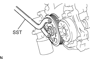
Hold the crankshaft with SST.
- SST
- 09960-10010 ( 09962-01000, 09963-01000 )
-

Remove the 6 bolts and flywheel sub-assembly.
-
-
REMOVE NO. 1 IGNITION COIL
-
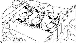
Disconnect the 3 connectors.
-
Remove the 3 bolts and 3 No. 1 ignition coils.
-
-
REMOVE SPARK PLUG
-
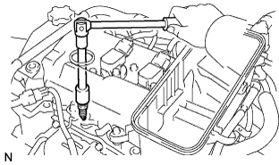
Remove the 3 spark plugs.
-
-
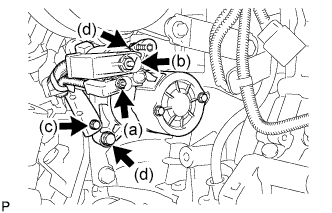
REMOVE GENERATOR ASSEMBLY
-
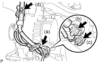
Remove the terminal cap.
-
Remove the nut and disconnect the wire harness from terminal B.
-
Remove the nut and disconnect the wire harness from terminal D.
-
Remove the bolt and disconnect the wire harness clamp from generator.
-
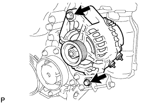
Remove the 2 bolts and generator.
-
-
REMOVE FAN BELT ADJUSTING BAR
-
Remove the bolt and fan belt adjusting bar from the timing chain or belt cover.
-
-
REMOVE EXHAUST MANIFOLD
-
Remove the 3 bolts, 2 nuts, and exhaust manifold.
-
Remove the exhaust manifold gasket.
-
-
REMOVE NO. 1 COMPRESSOR MOUNTING BRACKET (w/ Air Conditioning System)
-
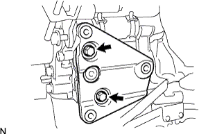
Remove the 2 bolts and No. 1 compressor mounting bracket.
-
-
REMOVE NO. 1 WATER BY-PASS PIPE
-
Remove the bolt and 2 nuts.
-
Loosen the hose clip and remove the No. 1 water by-pass pipe with water by-pass hose.
-
Remove the water by-pass pipe gasket.
-
-
REMOVE ENGINE OIL LEVEL DIPSTICK SUB-ASSEMBLY
-
REMOVE ENGINE OIL LEVEL DIPSTICK GUIDE
-
Disengage the 2 wire harness clamps from the engine oil level dipstick guide.
-
Remove the bolt and engine oil level dipstick guide.
-
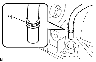
Text in Illustration *1 O-ring Remove the O-ring from the engine oil level dipstick guide.
-
-
REMOVE ENGINE OIL LEVEL DIPSTICK GUIDE SUPPORT
-
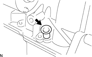
Remove the engine oil level dipstick guide support.
-
-
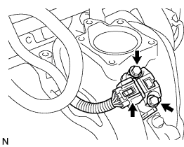
REMOVE THROTTLE BODY ASSEMBLY
-
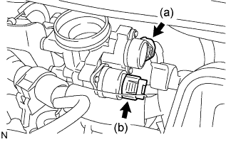
Disconnect the throttle position sensor connector.
-
Disconnect the idle speed control valve connector.
-
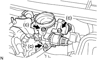
Remove the 3 bolts and throttle body.
-
-
REMOVE THROTTLE BODY GASKET
-
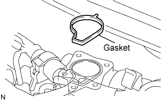
Remove the gasket from the intake manifold.
-
-
REMOVE FUEL DELIVERY PIPE
-
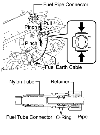
Disconnect the fuel earth cable from the heater hose pipe.
-
Remove the fuel pipe clamp from the fuel tube connector.
-
Pinch the tube connector and then pull out the fuel pipe.
Note
-
Check if there is any dirt or other foreign objects around the connector before this operation and clean the connector as necessary.
-
Be careful of mud because the quick connector has O-rings which seal the pipe and connector that can be contaminated.
-
Do not use any tool in this operation.
-
Do not bend or twist the nylon tube. Protect the connector by covering it with a plastic bag.
-
When the pipe and the connector are stuck, push and pull the connector to release and pull the connector out carefully.
-
-
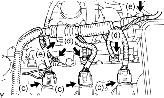
Disconnect the 3 ignition coil connectors.
-
Disconnect the 3 injector connectors.
-
Disconnect the 2 clamps and wire harness.
-
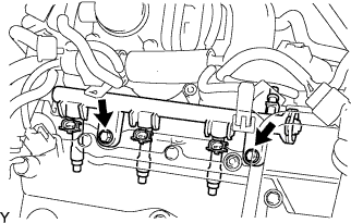
Remove the 2 bolts and delivery pipe together with the 3 injectors.
Note
Be careful not to drop the injectors when removing the delivery pipe.
-
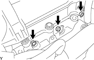
Remove the 3 injector vibration insulators from the cylinder head.
-
-
REMOVE FUEL INJECTOR ASSEMBLY
-
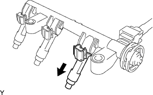
Pull out the 3 injectors from the fuel delivery pipe.
-
-
REMOVE VACUUM SENSOR
-
Disconnect the vacuum sensor connector.
-
Remove the 2 bolts and vacuum sensor.
-
-
REMOVE INTAKE MANIFOLD
-
Disconnect the PCV hose.
-
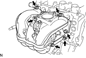
Remove the 4 bolts, 2 nuts, intake manifold stay and intake manifold.
-
Remove the intake manifold gasket from the intake manifold.
-
-
REMOVE THERMOSTAT
-
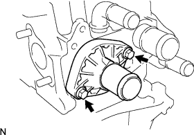
Remove the 2 bolts, water inlet, and thermostat.
-
Remove the thermostat gasket from the thermostat.
-
-
REMOVE CRANKSHAFT POSITION SENSOR
-
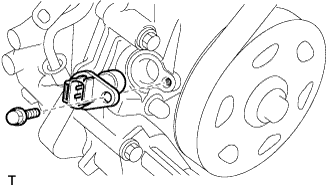
Disconnect the sensor connector.
-
Remove the bolt and sensor.
-
-
REMOVE CAMSHAFT TIMING OIL CONTROL VALVE ASSEMBLY
-
Disconnect the camshaft timing oil control valve connector.
-
Remove the bolt, then remove the camshaft timing oil control valve.
-
-
REMOVE OIL CONTROL VALVE FILTER
-
Using an 8 mm socket hexagon wrench, remove the head taper screw plug.
-
Remove the oil control valve filter and gasket.
-
-
REMOVE ENGINE OIL PRESSURE SWITCH ASSEMBLY
-
Disconnect the engine oil pressure switch assembly connector.
-
Text in Illustration *1 24 mm Deep Socket Wrench Using a 24 mm deep socket wrench, remove the oil pressure switch.
-
-
REMOVE KNOCK SENSOR
-
Disconnect the knock control sensor connector.
-
Remove the bolt and knock control sensor.
-
-
REMOVE CAMSHAFT POSITION SENSOR
-
Disconnect the sensor connector.
-
Remove the bolt and sensor.
-
-
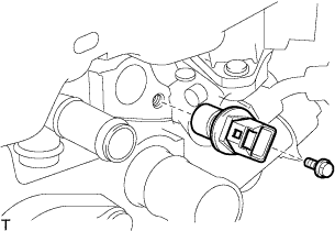
REMOVE ENGINE COOLANT TEMPERATURE SENSOR
-
Disconnect the engine coolant temperature sensor connector.
-
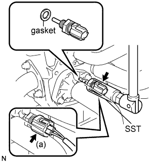
Using SST, remove the engine coolant temperature sensor and gasket.
- SST
- 09817-33190
-