ENGINE ASSEMBLY REMOVAL

-
DISCHARGE FUEL SYSTEM PRESSURE
-
Discharge the fuel system pressure Click here.
-
-
REMOVE BATTERY
-
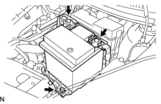
Disconnect the negative battery cable.
-
Disconnect the positive battery cable.
-
Remove the bolt, clamp, and battery.
-
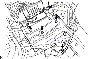
Remove the 4 bolts, clamp, and battery carrier.
Tech Tips
Remove the A bolt from the service hole on the battery carrier.
-
-
REMOVE FRONT WIPER ARM HEAD CAP
-
Remove the front wiper arm head cap Click here.
-
-
REMOVE FRONT WIPER ARM LH
-
Remove the front wiper arm LH Click here.
-
-
REMOVE HOOD TO COWL TOP SEAL
-
Remove the hood to cowl top seal Click here.
-
-
REMOVE COWL TOP VENTILATOR LOUVER RH
-
Remove the cowl top ventilator louver RH Click here.
-
-
REMOVE COWL TOP VENTILATOR LOUVER LH
-
Remove the cowl top ventilator louver LH Click here.
-
-
REMOVE FRONT WIPER MOTOR & LINK ASSEMBLY
-
Remove the front wiper motor & link assembly Click here.
-
-
REMOVE COWL TOP PANEL OUTER
-
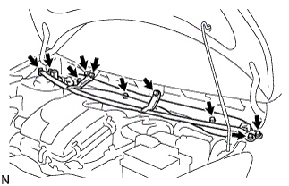
Remove the 10 bolts and cowl top panel outer.
-
-
DISCONNECT ENGINE WIRE
-
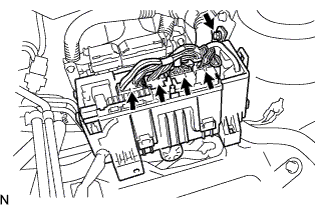
Disconnect the engine wire harness connectors from the engine room relay block.
-
Remove the bolt and engine room relay block.
-
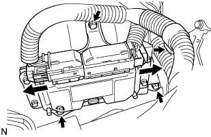
Disconnect the engine wire harness connectors from the ECM.
-
Disconnect the engine wire harness clamp.
-
Remove the 3 bolts and ECM.
-
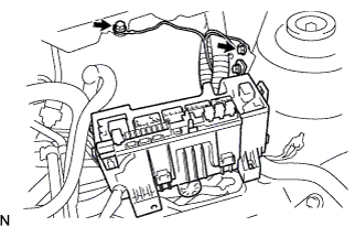
Remove the 2 bolts, then disconnect the 2 ground terminals.
-
Remove the nut, then disconnect the battery terminal B.
-
-
REMOVE AIR CLEANER CAP SUB-ASSEMBLY
-
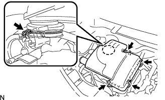
Disengage the air cleaner cap sub-assembly clamp.
-
Loosen the hose clamp, then remove the air cleaner cap sub-assembly.
-
Remove the air cleaner filter element from the air cleaner case.
-
Disconnect the throttle control cable from the throttle body.
-
-
REMOVE FUEL VAPOR FEED HOSE NO.1 AND NO.2
-
Disconnect the fuel vapor feed hoses No.1 and No.2.
-
Disconnect the VSV connector.
-
-
REMOVE ENGINE UNDER COVER
-
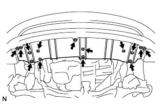
Remove the 9 bolts.
-
Remove the 5 screws and engine under cover.
-
-
REMOVE FRONT BUMPER COVER
-
Remove the front bumper cover Click here.
-
-
REMOVE FAN & GENERATOR V BELT
-
Remove the fan and generator V belt Click here.
-
-
DRAIN ENGINE COOLANT
-
Drain the engine coolant Click here.
-
-
REMOVE FRONT EXHAUST PIPE ASSEMBLY
-
Remove the front exhaust pipe assembly Click here.
-
-
REMOVE RADIATOR HOSE INLET
-
REMOVE RADIATOR HOSE OUTLET
-
REMOVE FRONT CROSS MEMBER SUB-ASSEMBLY
-
Remove the front cross member sub-assembly Click here.
-
-
REMOVE RADIATOR ASSEMBLY
-
Remove the radiator assembly Click here.
-
-
REMOVE W/ MOTOR FAN ASSEMBLY
-
Remove the w/ motor fan assembly Click here.
-
-
SEPARATE W/ PULLEY COMPRESSOR ASSEMBLY (W/ AIR CONDITIONER)
Tech Tips
Move the compressor and A/C hoses to the side of the engine to prevent them from interfering with other parts in the following procedure.
-
Separate the w/ pulley compressor assembly (w/ air conditioner) Click here.
-
-
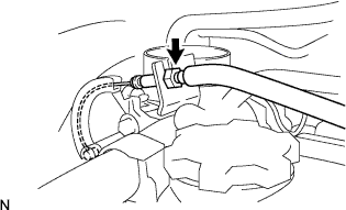
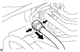
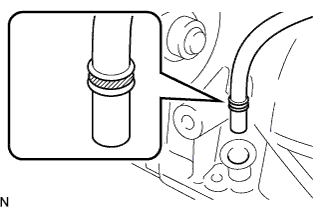
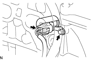
DISCONNECT VACUUM HOSE ASSEMBLY
-
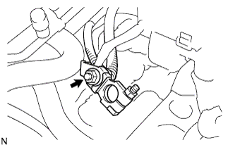
Pinch the retainer as illustrated, then pull out the vacuum hose connector from the pipe.
-
-
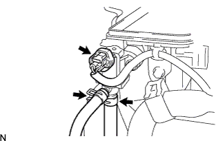
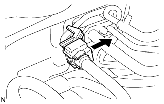
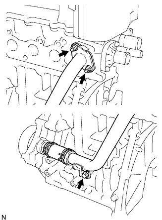
DISCONNECT HEATER WATER HOSE INLET A
-
Using pliers, grip the claws of the clip and slide the clip to disconnect the heater water inlet hose A.
-
-
DISCONNECT HEATER WATER OUTLET HOSE A (FROM HEATER UNIT)
Tech Tips
Disconnection procedure for the heater water outlet hose A is the same as for the heater water inlet hose A.
-
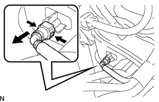
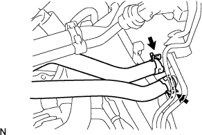
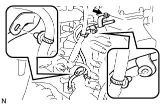
REMOVE FUEL TUBE SUB-ASSEMBLY
-
Remove the fuel pipe clamp.
-
Pinch the retainer as illustrated, then pull out the fuel tube connector from the pipe.
Note
-
Remove any dirt and foreign objects on the fuel tube connector before performing this work.
-
Do not allow any scratches or foreign objects on the O-rings of the fuel tube connector, otherwise the pipe may not be sealed properly.
-
Perform this work by hand. Do not use any tools.
-
Do not forcibly bend, twist, or turn the nylon tube.
-
Protect the disconnected part by covering it with a vinyl bag after disconnecting the fuel tube.
-
If the fuel tube connector and pipe are stuck, separate them by pushing and pulling on the connection.
-
-
-
SEPARATE TRANSAXLE CONTROL CABLE ASSEMBLY
-
Separate the transaxle control cable assembly Click here.
-
-
SEPARATE CLUTCH RELEASE CABLE ASSEMBLY
-
Separate the clutch release cable assembly Click here.
-
-
PLACE FRONT WHEELS FACING STRAIGHT A HEAD
-
REMOVE STEERING COLUMN HOLE COVER PLATE
-
Remove the steering column hole cover plate Click here.
-
-
SEPARATE STEERING INTERMEDIATE SHAFT ASSEMBLY NO.2
-
Separate the steering intermediate shaft assembly No.2 Click here.
-
-
DRAIN MANUAL TRANSAXLE OIL
-
Drain the manual transaxle oil Click here.
-
-
REMOVE FRONT WHEELS
-
REMOVE FRONT AXLE HUB NUT RH
-
Remove the front axle hub nut RH Click here.
-
-
REMOVE FRONT AXLE HUB NUT LH
-
Remove the front axle hub nut LH Click here.
-
-
SEPARATE TIE ROD END SUB-ASSEMBLY RH
- SST
- 09611-12010
-
Separate the tie rod end sub-assembly RH Click here.
-
SEPARATE TIE ROD END SUB-ASSEMBLY LH
- SST
- 09611-12010
-
Separate the tie rod end sub-assembly LH Click here.
-
SEPARATE FRONT SUSPENSION ARM SUB-ASSEMBLY LOWER RH
- SST
- 09628-00011
-
Separate the front suspension arm sub-assembly lower RH Click here.
-
SEPARATE FRONT SUSPENSION ARM SUB-ASSEMBLY LOWER LH
- SST
- 09628-00011
-
Separate the front suspension arm sub-assembly lower LH Click here.
-
REMOVE FRONT DRIVE SHAFT ASSEMBLY RH
- SST
- 09930-00010
-
Remove the front drive shaft assembly RH Click here.
-
REMOVE FRONT DRIVE SHAFT ASSEMBLY LH
- SST
- 09930-00010
-
Remove the front drive shaft assembly LH Click here.
-
REMOVE ENGINE ASSEMBLY W/ TRANSAXLE
-
Set the engine lifter.
-
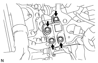
Remove the 4 bolts from the engine mounting insulator RH.
-
Remove the nut and engine mounting insulator RH.
-
Remove the 4 bolts from the engine mounting insulator LH.
-
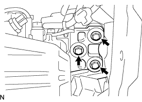
Remove the 3 bolts and engine mounting insulator LH.
-
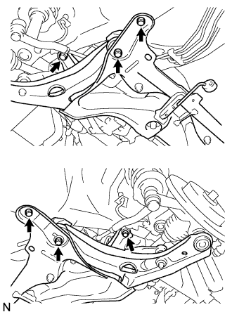
Remove the 6 bolts.
-
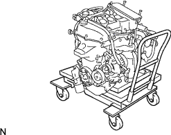
Remove the engine assembly with transaxle.
-
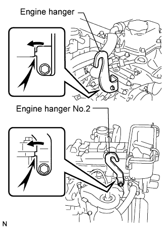
Install the engine hanger (12281-40030) with the bolt (91671-80820).
- Torque:
- 28 N*m { 285 kgf*cm, 21 ft.*lbf }
Tech Tips
-
Securely install the front engine hanger (12281-40030) to the engine assembly.
-
Be sure to hold down on the stopper when installing the engine hanger.
-
Install the engine hanger No.2 (12282-40010) with the bolt (91671-80820).
- Torque:
- 28 N*m { 285 kgf*cm, 21 ft.*lbf }
Tech Tips
-
Securely install the front engine hanger No.2 (12282-40010) to the engine assembly.
-
Be sure to hold down on the stopper when installing the engine hanger.
-
Attach the engine sling and hang the engine with the chain block.
-
-
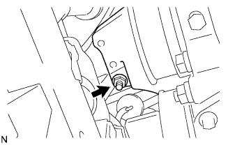
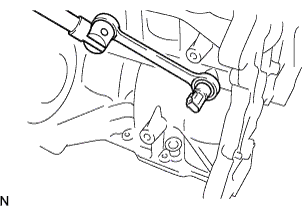
SEPARATE FRONT SUSPENSION CROSS MEMBER SUB-ASSEMBLY
-
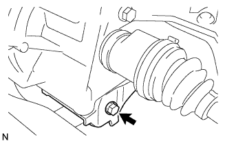
Remove the bolt, then separate the engine assembly with transaxle from the front suspension cross member assembly.
-
-
REMOVE STARTER ASSEMBLY
-
Remove the starter assembly Click here, Click here.
-
-
REMOVE MANUAL TRANSAXLE ASSEMBLY
-
Remove the manual transaxle assembly Click here.
-
-
REMOVE CLUTCH COVER ASSEMBLY
-
Remove the clutch cover assembly Click here.
-
-
REMOVE CLUTCH DISC ASSEMBLY
-
Remove the clutch disc assembly Click here.
-
-
REMOVE FLYWHEEL SUB-ASSEMBLY
-
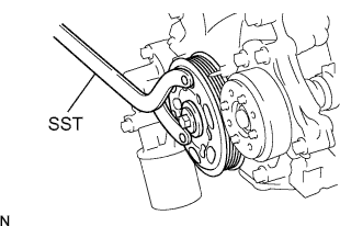
Hold the crankshaft with SST.
- SST
- 09960-10010 ( 09962-01000, 09963-01000 )
-

Remove the 6 bolts and flywheel sub-assembly.
-
-
REMOVE IGNITION COIL NO.1
-
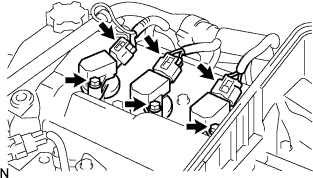
Disconnect the 3 connectors.
-
Remove the 3 bolts and 3 ignition coils.
-
-
REMOVE SPARK PLUG
-
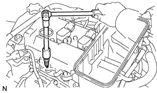
Remove the 3 spark plugs.
-
-
REMOVE GENERATOR ASSEMBLY
-
Remove the generator assembly Click here.
-
-
REMOVE FAN BELT ADJUSTING BAR
-
Remove the fan belt adjusting bar Click here.
-
-
REMOVE EXHAUST MANIFOLD
-
Disconnect the oxygen sensor connector.
-
Remove the 3 bolts, 2 nuts, and exhaust manifold.
-
Remove the exhaust manifold gasket.
-
-
REMOVE COMPRESSOR MOUNTING BRACKET NO.1 (W/ AIR CONDITIONER)
-
Remove the 2 bolts and compressor mounting bracket.
-
-
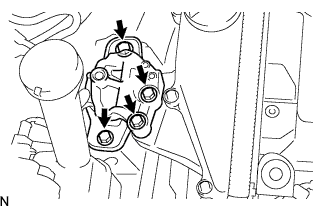
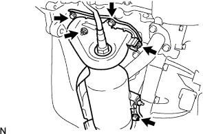
REMOVE WATER BY-PASS PIPE NO.1
-
Remove the bolt and 2 nuts.
-
Remove the bolt and clamp, then remove the water by-pass pipe No.1.
-
Remove the clamp, then remove the water by-pass hose from the water by-pass pipe No.1.
-
Remove the water by-pass pipe gasket.
-
-
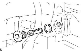
REMOVE OIL LEVEL GAUGE SUB-ASSEMBLY
-
REMOVE OIL LEVEL GAUGE GUIDE
-
Disconnect the 2 clamps from the oil level gauge guide.
-
Remove the bolt and oil level gauge guide.
-
Remove the O-ring from the oil level gauge guide.
-
-
REMOVE OIL LEVEL GAUGE GUIDE SUPPORT
-
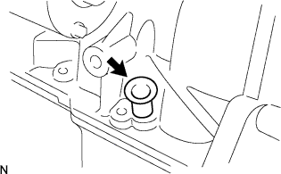
Remove the oil level gauge guide support.
-
-
REMOVE THROTTLE BODY ASSEMBLY
-
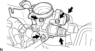
Disconnect the throttle body assembly connector.
-
Remove the 3 bolts and throttle body assembly.
-
Remove the throttle body gasket from the intake manifold.
-
-
REMOVE FUEL DELIVERY PIPE
-
Remove the fuel delivery pipe Click here.
-
-
REMOVE FUEL INJECTOR
-
Remove the fuel injector Click here.
-
-
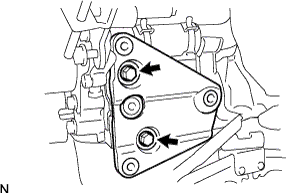
REMOVE VACUUM SENSOR
-
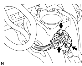
Disconnect the vacuum sensor connector.
-
Remove the 2 bolts and vacuum sensor.
-
-
REMOVE INTAKE MANIFOLD
-
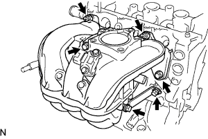
Disconnect the PCV hose.
-
Remove the 4 bolts, 2 nuts, and intake manifold.
-
Remove the intake manifold gasket from the intake manifold.
-
-
REMOVE THERMOSTAT
-
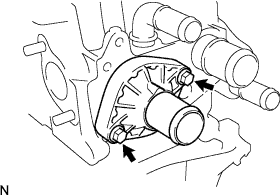
Remove the 2 bolts, inlet water, and thermostat.
-
Remove the thermostat gasket from the thermostat.
-
-
REMOVE CRANKSHAFT POSITION SENSOR
-
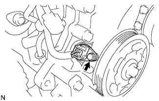
Disconnect the crankshaft position sensor connector.
-
Remove the bolt and crankshaft position sensor.
-
-
REMOVE CAMSHAFT TIMING OIL CONTROL VALVE ASSEMBLY
-
Disconnect the camshaft timing oil control valve assembly connector.
-
Remove the bolt and camshaft timing oil control valve assembly.
-
-
REMOVE OIL CONTROL VALVE FILTER
-
Using the hexagon wrench, remove the oil control valve filter.
-
Remove the oil control valve filter gasket.
-
-
REMOVE ENGINE OIL PRESSURE SWITCH ASSEMBLY
-
Disconnect the engine oil pressure switch assembly connector.
-
Remove the engine oil pressure switch assembly.
-
-
REMOVE KNOCK CONTROL SENSOR
-
Disconnect the knock control sensor connector.
-
Remove the bolt and knock control sensor.
-
-
REMOVE CAMSHAFT POSITION SENSOR
-
Disconnect the camshaft position sensor connector.
-
Remove the bolt and camshaft position sensor.
-
-
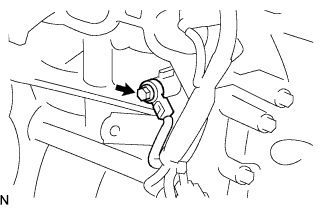
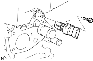
REMOVE E.F.I. ENGINE COOLANT TEMPERATURE SENSOR
-
Disconnect the E.F.I. engine coolant temperature sensor connector.
-
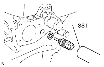
Using SST, remove the E.F.I. engine coolant temperature sensor and gasket.
- SST
- 09817-33190
Note
Do not use parts that have been dropped or received strong impact.
-