CAMSHAFT INSTALLATION

-
INSTALL CAMSHAFTS
-
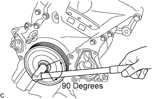
Turn the crankshaft by approximately 90 degrees in direction of engine revolution from the TDC for No.1 cylinder so that the lifted valve and piston do not contract each other when installing the camshaft assembly.
-
Install the camshaft assembly No.1 and No.2.
-
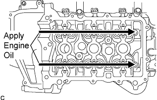
Apply engine oil to the cam of each camshaft assembly, journals of the cylinder head assembly and top of each valve lifter.
-
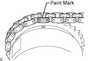
Align the matchmarks on the timing chain plates with the timing mark of the camshaft timing sprocket assembly (VVT controller) and the paint mark of the timing chain respectively and install the timing chain.
-
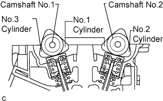
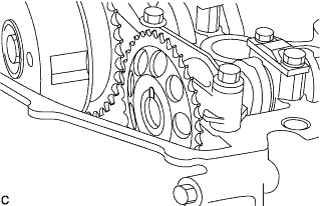
Install the camshaft assembly No.1 as shown in the illustration.
Tech Tips
Make sure that the timing marks of the camshaft timing sprocket and camshaft timing sprocket assembly (VVT controller) face upward.
-
-
-
INSTALL CAMSHAFT BEARING CAP
-
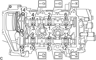
Place the camshaft bearing caps No.1 and No.2 and tighten the bolts to the specified torque in the order shown in the illustration.
- Torque:
- Camshaft bearing cap No.1
- 15 N*m { 153 kgf*cm, 11 ft.*lbf }
- Camshaft bearing cap No.2
- 12.5 N*m { 128 kgf*cm, 9 ft.*lbf }
Note
Be sure to install the camshaft bearing caps No.1 and No.2 with the front marks facing engine front.
-
-
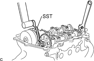
INSTALL CAMSHAFT TIMING GEAR OR SPROCKET
-

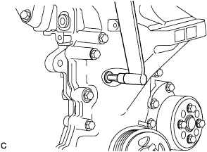
Using SST, tighten the bolts to install the sprocket assembly while holding the hexagonal portion of the camshaft assembly No.1.
- SST
- 09249-B1010
- Torque:
- 35 N*m { 356 kgf*cm, 26 ft.*lbf }
Note
Use a torque wrench with a fulcrum length of 345 mm (13.58 in.).
Tech Tips
The reading of the torque wrench should be calculated because the torque wrench must be joined with the SST for use.
-
Install the camshaft assembly No.2 with the knock pin aligning with the gear groove.
Tech Tips
Make sure that the matchmark of the gear is at the top.
-
Tighten the bolts to install the sprocket while holding the hexagonal portion of the camshaft assembly No.2.
- SST
- 09249-B1010
- Torque:
- 35 N*m { 356 kgf*cm, 26 ft.*lbf }
Note
Use a torque wrench with a fulcrum length of 345 mm (13.58 in.).
Tech Tips
The reading of the torque wrench should be calculated because the torque wrench must be joined with the SST for use.
-
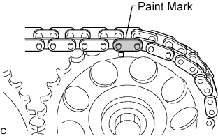
Align the matchmarks on the timing chain plates with the timing mark of the camshaft timing sprocket and the paint mark of the timing chain respectively and install the timing chain.
-
Remove SST from the timing chain tensioner sub-assembly.
Tech Tips
Before removing, slightly turn the hexagonal portion of the camshaft assembly counterclockwise to leave some slack on the chain of the timing chain tensioner sub-assembly side.
-
-
INSTALL TIMING GEAR COVER TIGHT PLUG
-
Clean the plug and the bolt holes of the timing chain cover assembly and apply adhesive to the threads of the plug.
- Torque:
- 15 N*m { 153 kgf*cm, 11 ft.*lbf }
-
-
INSTALL CYLINDER HEAD COVER SUB-ASSEMBLY
-
Clean the cylinder head cover, cylinder head assembly and timing chain cover assembly.
-
Fit the cylinder head cover gasket into the gasket groove on the cover and onto the center bosses.
-
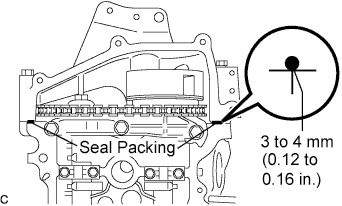
Apply a continuous bead of seal gasket (diameter: 3 to 4 mm (0.12 to 0.16 in.)) to the contact surface between the cylinder head assembly and timing chain cover assembly as shown in the illustration.
Seal Packing Part No.08826-00080 or equivalent -
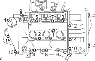
Install the bolts within 3 minutes after applying seal gasket in the order shown in the illustration. Tighten the bolts to the specified torque and make sure that bolts "1" and "2" are tightened to the specified torque.
- Torque:
- 7.7 N*m { 79 kgf*cm, 68 in.*lbf }
-
Connect the ventilation hose.
-
-
INSTALL IGNITION COIL NO.1
-
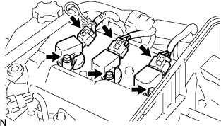
Install the 3 ignition coils with the 3 bolts.
- Torque:
- 8.9 N*m { 91 kgf*cm, 79 in.*lbf }
-
Connect the ignition coil assembly connectors.
-
-
INSTALL FUEL VAPOR FEED HOSE NO.1 AND NO.2
-
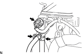
Connect the VSV connector.
-
Connect the fuel vapor feed hose No.1 and No.2.
-
-
INSTALL FAN & GENERATOR V BELT
Install the fan and generator V belt Click here.
-
INSTALL FRONT BUMPER COVER
Install the front bumper cover Click here.
-
INSTALL AIR CLEANER CAP SUB-ASSEMBLY
-
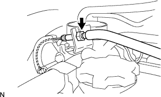
Connect the throttle control cable to the throttle body.
- Torque:
- 13 N*m { 133 kgf*cm, 9.6 ft.*lbf }
-
Install the air cleaner filter element.
-
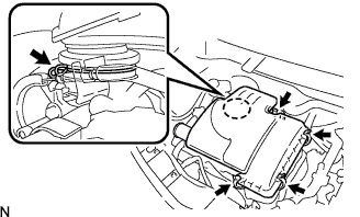
Install the air cleaner cap sub-assembly.
-
Tighten the hose clamp bolt.
-
Engage the air cleaner cap sub-assembly clamp.
-
-
CONNECT CABLE TO NEGATIVE BATTERY TERMINAL
- Torque:
- 5.4 N*m { 55 kgf*cm, 48 in.*lbf }
-
INSPECT ENGINE OIL LEAKS