CAMSHAFT REMOVAL

-
DISCONNECT CABLE FROM NEGATIVE BATTERY TERMINAL
-
REMOVE AIR CLEANER CAP SUB-ASSEMBLY
-
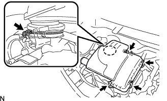
Disengage the air cleaner cap sub-assembly clamp.
-
Loosen the hose clamp bolt, then remove the air cleaner cap sub-assembly.
-
Remove the air cleaner filter element from the air cleaner case.
-
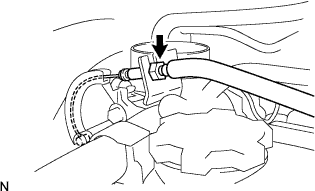
Disconnect the throttle control cable from the throttle body.
-
-
REMOVE FRONT BUMPER COVER
-
Remove the front bumper cover Click here.
-
-
REMOVE FAN & GENERATOR V BELT
-
Remove the fan and generator V belt Click here.
-
-
DISCONNECT FUEL VAPOR FEED HOSE NO.1 AND NO.2
-
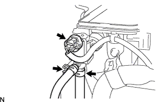
Disconnect the fuel vapor feed hose No.1 and No.2.
-
Disconnect the VSV connector.
-
-
REMOVE IGNITION COIL NO.1
-
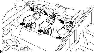
Disconnect the ignition coil connectors.
-
Remove the 3 bolts and the ignition coils.
-
-
REMOVE CYLINDER HEAD COVER SUB-ASSEMBLY
-
Disconnect the ventilation hose.
-
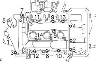
Remove the 13 bolts and 2 nuts in the order shown in the illustration, then remove the cylinder head cover sub-assembly.
-
-
REMOVE TIMING GEAR COVER TIGHT PLUG
-
Using a socket wrench 10 mm, remove the timing gear cover tight plug from the timing chain cover.
-
-
REMOVE CAMSHAFT TIMING GEAR OR SPROCKET
-
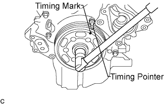
Turn the crankshaft pulley assembly clockwise to align the timing mark on the pulley assembly (0 degree) with the timing pointer of the timing chain (Set the No.1 piston to the TDC/exhaust).
-
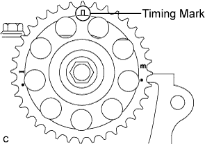
Make sure that the timing mark of the camshaft sprocket is at the top.
Tech Tips
If the timing mark is not at the top, turn the crankshaft pulley assembly 1 revolution so that the timing mark comes to the top (Set the No.1 piston to the TDC/exhaust).
-
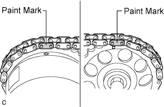
Put matchmarks on each plate of the timing chain where the plates are aligned with the matchmarks on the sprockets and camshaft timing sprocket assembly (VVT controller).
Tech Tips
There are two orange mark plates and a yellow mark plate on the timing chain. If the orange mark plates are aligned with the cam sprockets and the yellow mark plate is aligned with the crankshaft, this step can be omitted.
-
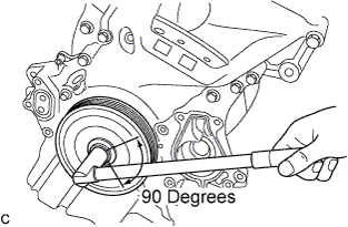
Turn the crankshaft by approximately 90 degrees in the engine revolution direction at the point where the No.1 piston is set to the TDC/exhaust so that the lifted valve and piston do not contact each other when removing the camshaft assembly.
-
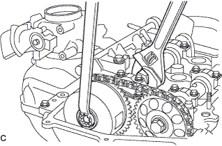
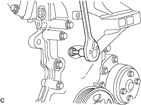
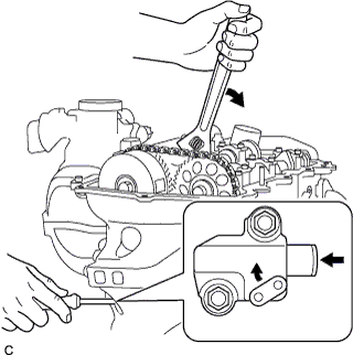
Loosen the bolts on the sprocket assembly while holding the hexagonal portion of the camshaft assembly.
-
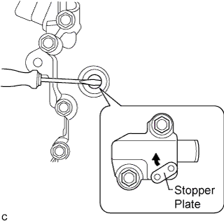
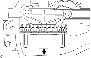
Insert a screwdriver from the plug hole and turn the stopper plate of the timing chain tensioner sub-assembly clockwise to release the lock, and keep it as it is.
Tech Tips
-
The plunger of the timing chain tensioner sub-assembly is locked.
-
If the stopper plate is locked firmly, slightly turn the hexagonal portion of the camshaft assembly to the right and left.
-
-
Slightly turn the hexagonal portion of the camshaft assembly clockwise so that the plunger of the timing chain tensioner sub-assembly is pushed by the timing chain.
-
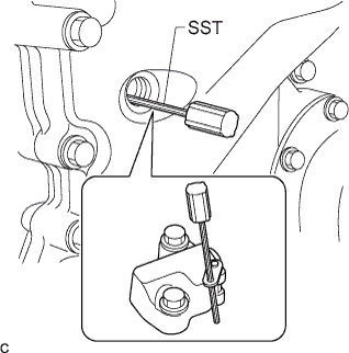
Remove the screwdriver from the plug. Insert the SST into the stopper plate hole.
- SST
- 09240-00020 ( 09242-00200 )
Note
-
Be sure to hold the hexagonal portion of the camshaft assembly.
-
Fix the SST with tape or equivalent to prevent it from coming off.
Tech Tips
Perform this procedure in order to keep the plunger being pushed by the timing chain tensioner sub-assembly.
-
Remove the sprocket from the camshaft assembly No.2.
-
-
REMOVE CAMSHAFT BEARING CAP
-
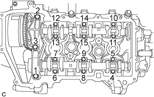
Remove the bolts in the order shown in the illustration.
-
Remove the camshaft bearing caps No.1 and No.2.
-
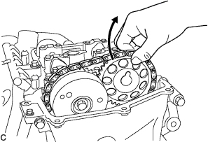
Slide the camshaft timing sprocket assembly toward engine front until the camshaft bearing cap No.1 comes off.
-
Remove the camshaft bearing caps No.1 and No.2.
-
-
-
REMOVE CAMSHAFTS
-
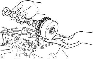
Remove the camshaft assembly No.1 and No.2.
Tech Tips
-
Be sure to remove the camshaft assembly No.1 along with the camshaft timing sprocket.
-
Be sure to assemble the camshaft timing sprocket to the camshaft assembly No.1 before installing them.
-
-
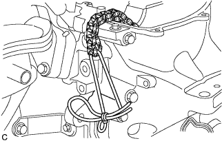
Using a string or equivalent, fix the timing chain to prevent it from dropping.
-