ECD SYSTEM, Diagnostic DTC:P0201, P0202, P0203, P0204, P1366, P1367, P1368, P1369

| DTC Code | DTC Name |
|---|---|
| P0201 | Piezoelectric Injection Timing Cylinder 1 |
| P0202 | Piezoelectric Injection Timing Cylinder 2 |
| P0203 | Piezoelectric Injection Timing Cylinder 3 |
| P0204 | Piezoelectric Injection Timing Cylinder 4 |
| P1366 | Injector Piezoelectric Voltage / Current / Charge Cylinder 1 |
| P1367 | Injector Piezoelectric Voltage / Current / Charge Cylinder 2 |
| P1368 | Injector Piezoelectric Voltage / Current / Charge Cylinder 3 |
| P1369 | Injector Piezoelectric Voltage / Current / Charge Cylinder 4 |
DESCRIPTION
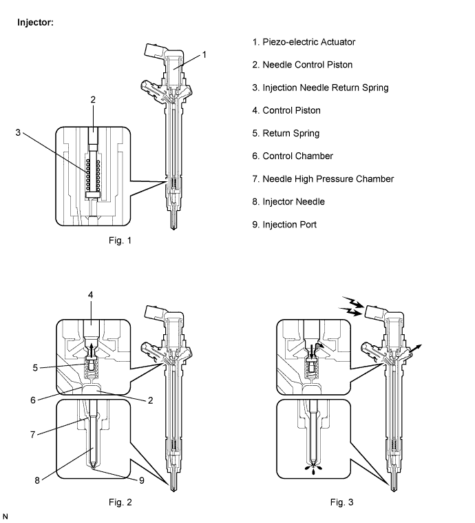
The injector injects the amount of the fuel calculated by the ECM into each cylinder.
A piezo-electric actuator, which is built into the injector, has characteristics that allow a fast response when voltage (70 V) is applied. Therefore, fuel injection can be performed quickly and accurately. (Refer to Fig. 1)
When no voltage is applied to the injector, the control piston is pressed to the top due to the force of the return spring. As a result, the fuel pressure values in the control chamber and the needle high pressure chamber become the same, and the needle control piston and injector needle are pressed downward due to the force of the return spring. Therefore, the injection needle is closed to stop fuel injection. (Refer to Fig. 2)
When voltage is applied to the injector, the piezo-electric actuator presses down the control piston. The pressure in the control chamber decreases because the high-pressure fuel in the control chamber is discharged. The fuel pressure in the needle high pressure chamber exceeds the force of the injection needle return spring, and the needle control piston and the injector needle are pressed upward to start fuel injection from the injection port. (Refer to Fig.3)
When voltage being applied to the injector is stopped, the needle control piston and the injector needle are pressed down again to close the injection port and stop fuel injection.
| DTC No. | DTC Detection Condition | Trouble Area | Possible to Detect | |
|---|---|---|---|---|
| Ignition Switch | Engine Run | |||
| P0201 | Injector circuit fault (Cylinder 1) (1 trip detection logic) |
|
ON | ON |
| P0202 | Injector circuit fault (Cylinder 2) (1 trip detection logic) |
|
ON | ON |
| P0203 | Injector circuit fault (Cylinder 3) (1 trip detection logic) |
|
ON | ON |
| P0204 | Injector circuit fault (Cylinder 4) (1 trip detection logic) |
|
ON | ON |
| P1366 | Injector circuit fault (Cylinder 1) (1 trip detection logic) |
|
ON | ON |
| P1367 | Injector circuit fault (Cylinder 2) (1 trip detection logic) |
|
ON | ON |
| P1368 | Injector circuit fault (Cylinder 3) (1 trip detection logic) |
|
ON | ON |
| P1369 | Injector circuit fault (Cylinder 4) (1 trip detection logic) |
|
ON | ON |
-
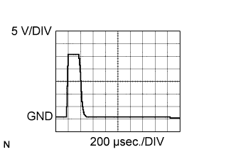
Reference:
-
The waveform between terminals #10 to #40 and PINJ1 to PINJ4 of the ECM connectors with the engine idling.
CAUTION:
-
Do not reuse the injection pipe. Be sure to replace it with a new one.
-
Do not reuse the injection nozzle seat. If the injector has been removed, be sure to replace the injector nozzle seat with a new one.
-
The injector is controlled by a voltage of +/- 70 V.
-
Be sure to connect the injector connectors correctly to prevent malfunctions in the injector.
-
Do not use any power source other than the ECM for the injector.
-
Do not apply voltage to the injector while it is not grounded to body.
-
Do not disassemble the injector.
-
Do not use the ultrasonic cleaning tool to clean the injector.
FAIL-SAFE
| DTC No. | Trouble Area | Possible to Detect |
|---|---|---|
| P0201 | Stops the malfunctioning injector. | Normal condition is restored at the next engine start. |
| P0202 | Stops the malfunctioning injector. | Normal condition is restored at the next engine start. |
| P0203 | Stops the malfunctioning injector. | Normal condition is restored at the next engine start. |
| P0204 | Stops the malfunctioning injector. | Normal condition is restored at the next engine start. |
| P1366 | Stops the malfunctioning injector. | Normal condition is restored at the next engine start. |
| P1367 | Stops the malfunctioning injector. | Normal condition is restored at the next engine start. |
| P1368 | Stops the malfunctioning injector. | Normal condition is restored at the next engine start. |
| P1369 | Stops the malfunctioning injector. | Normal condition is restored at the next engine start. |
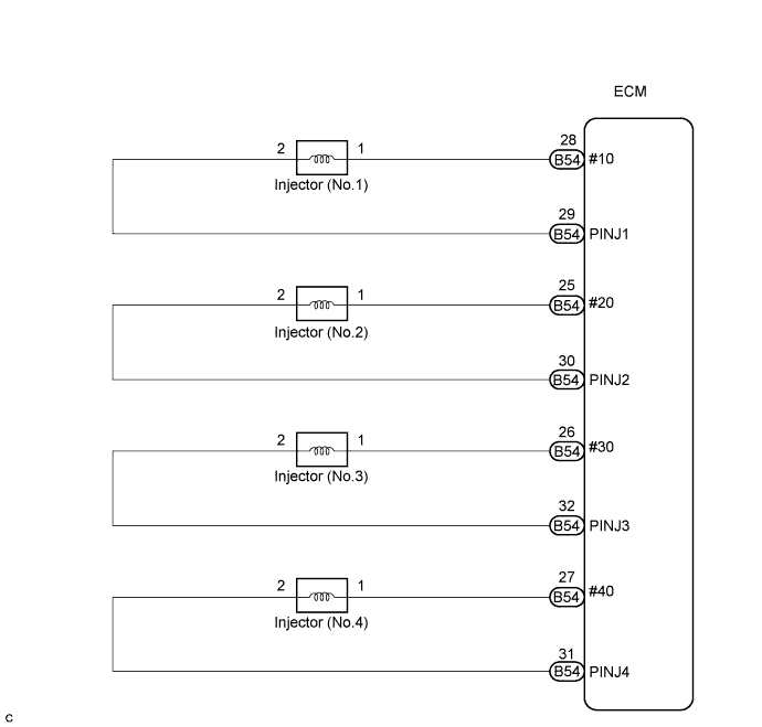
WIRING DIAGRAM
INSPECTION PROCEDURE
Tech Tips
-
When DTC P0201, P0202, P0203, P0204 P1366, P1367, P1368 or P1369 is detected, check the injector voltage by selecting the following menu items on the intelligent tester: Powertrain / Engine and ECT / Data List / Inj Volt.
-
If the ECM is replaced, variant coding (variant coding indicates the presence of vehicle accessory items, A/C, etc.) should always be performed Click here.
-
Before removing the ECM and the peripheral parts, wait at least 3 minute after turning the ignition switch off (If the cooling fan is operating, remove the ECM and the peripheral parts after the fan stops.).
PROCEDURE
-
CHECK INJECTOR
-
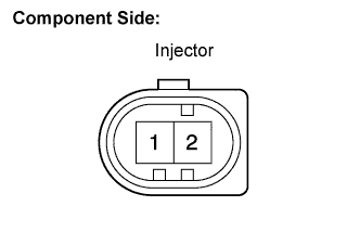
Disconnect the N1, N2, N3 and N4 injector connectors.
-
Measure the resistance according to the value(s) in the table below.
Standard resistance Tester Connection Specified Condition 1 - 2 150 to 250 kΩ
NG 
REPLACE INJECTOR (S)
OK 
-
-
CHECK CONNECTORS (INSTALLATION)
-
Check the installation condition the ECM and injector connector.
OK The connectors all installed correctly.
NG
REPAIR OR REPLACE CONNECTOR
OK
-
-
CHECK HARNESS AND CONNECTOR (INJECTOR - ECM)
-
Disconnect the B54 ECM connector.
-
Disconnect the N1, N2, N3 and N4 injector connectors.
-
Measure the resistance according to the value(s) in the table below.
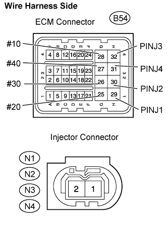
Standard resistance Check for open Tester Connection Specified Condition #10 (B54-28) - Injector (No.1) (N1-1) Below 1 Ω PINJ1 (B54-29) - Injector (No.1) (N1-2) Below 1 Ω #20 (B54-25) - Injector (No.2) (N2-1) Below 1 Ω PINJ2 (B54-30) - Injector (No.2) (N2-2) Below 1 Ω #30 (B54-26) - Injector (No.3) (N3-1) Below 1 Ω PINJ3 (B54-32) - Injector (No.3) (N3-2) Below 1 Ω #40 (B54-27) - Injector (No.4) (N4-1) Below 1 Ω PINJ4 (B54-31) - Injector (No.4) (N4-2) Below 1 Ω Check for short Tester Connection Specified Condition #10 (B54-28) or Injector (No.1) (N1-1) - Body ground 10 kΩ or higher PINJ1 (B54-29) or Injector (No.1) (N1-2) - Body ground 10 kΩ or higher #20 (B54-25) or Injector (No.2) (N2-1) - Body ground 10 kΩ or higher PINJ2 (B54-30) or Injector (No.2) (N2-2) - Body ground 10 kΩ or higher #30 (B54-26) or Injector (No.3) (N3-1) - Body ground 10 kΩ or higher PINJ3 (B54-32) or Injector (No.3) (N3-2) - Body ground 10 kΩ or higher #40 (B54-27) or Injector (No.4) (N4-1) - Body ground 10 kΩ or higher PINJ4 (B54-31) or Injector (No.4) (N4-2) - Body ground 10 kΩ or higher
NG
REPAIR OR REPLACE HARNESS OR CONNECTOR
OK 
REPLACE ECM
-