ECD SYSTEM, Diagnostic DTC:P0111, P0112, P0113

| DTC Code | DTC Name |
|---|---|
| P0111 | Intake Air Temperature Sensor Gradient Too High |
| P0112 | Short to GND in Intake Air Temperature Sensor Circuit |
| P0113 | Open or Short to B+ in Intake Air Temperature Sensor Circuit |
DESCRIPTION
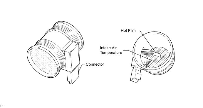
Located between the air cleaner filter and the turbocharger, the mass air flow meter measures the mass of intake air flowing into the engine.
The MAF also measures the temperature of the air flowing into the engine.
The intake air temperature sensor in the air flow meter is composed of an NTC (Negative Temperature Coefficient) type thermistor.
Based on this information, the ECM:
-
Calculates the theoretical air volume.
-
Calculates the injection advance.
-
Calculates the injection flow.
-
Triggers additional heating.
CAUTION:
Do not touch the hot film because it is easily broken.
DTC No. DTC Detection Condition Trouble Area Possible to Detect Ignition Switch Engine Run P0111 The output from the intake air temperature sensor suddenly changes for 1.5 sec. or more.
(3 trip detection logic)
-
Mass air flow meter
-
Mass air flow meter circuit
-
ECM
ON ON P0112 Mass air flow meter (intake air temperature) sensor output is more than 130°C (266°F) (less than 0.18 V) for 10 sec. or more.
(3 trip detection logic)
-
Mass air flow meter
-
Mass air flow meter circuit
-
ECM
ON ON P0113 Mass air flow meter (intake temperature) sensor output is less than -40°C (-40°F) (more than 4.78 V) for 10 sec. or more.
(3 trip detection logic)
-
Mass air flow meter
-
Mass air flow meter circuit
-
ECM
ON ON -
FAIL-SAFE
| DTC No. | Fail-safe Operation | Fail-safe Deactivation Condition |
|---|---|---|
| P0111 | A value of 40°C (104°F) is used as the intake air temperature. | Normal condition is restored. |
| P0112 | A value of 40°C (104°F) is used as the intake air temperature. | Normal condition is restored. |
| P0113 | A value of 40°C (104°F) is used as the intake air temperature. | Normal condition is restored. |
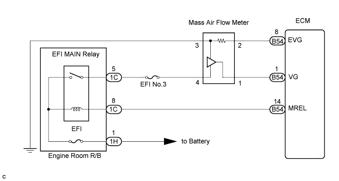
WIRING DIAGRAM
INSPECTION PROCEDURE
Tech Tips
-
When DTC P0111, P0112 or P0113 is detected, check the intake air temperature by selecting the following menu items on the intelligent tester: Powertrain / Engine and ECT / Data List / Intake Air Temp.
Displayed (Temperature) Malfunction Less than -40°C (-40°F) Open or short to +B circuit More than 130°C (266°F) Short to ground -
If the ECM is replaced, variant coding (variant coding indicates the presence of vehicle accessory items, A/C, etc.) should always be performed Click here.
-
Before removing the ECM and the peripheral parts, wait at least 3 minute after turning the ignition switch off (If the cooling fan is operating, remove the ECM and the peripheral parts after the fan stops.).
PROCEDURE
-
READ VALUE OF INTELLIGENT TESTER (INTAKE AIR TEMPERATURE)
-
Warm up the engine.
-
Connect the intelligent tester to the DLC3.
-
Turn the ignition switch to the ON position and turn the intelligent tester on.
-
Select the following menu items: Powertrain / Engine and ECT / Intake Air Temp.
-
Read the value.
OK The displayed temperature is the same as the actual intake air temperature, and the sensor output does not fluctuate significantly. Tech Tips
-
If there is an open circuit, the intelligent tester indicates less than -40°C (-40°F).
-
If there is a short circuit to ground, the intelligent tester indicates more than 130°C (266°F).
-
NG 
CHECK MASS AIR FLOW METER (INTAKE AIR TEMPERATURE SENSOR) Click here
OK 
CHECK FOR INTERMITTENT PROBLEMS
-
-
CHECK MASS AIR FLOW METER (INTAKE AIR TEMPERATURE SENSOR)
-
Disconnect the B40 mass air flow meter connector.
-
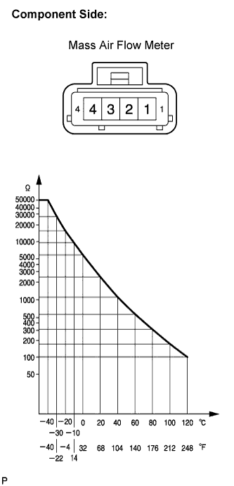
Measure the resistance according to the value(s) in the table below.
Standard resistance Tester Connection Specified Condition 2 - 3 The resistance value is within the acceptable range shown in the illustration.
NG 
REPLACE MASS AIR FLOW METER (INTAKE AIR TEMPERATURE SENSOR)
OK 
-
-
INSPECT ECM (VOLTAGE)
-
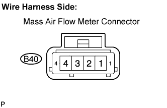
Disconnect the B40 mass air flow meter connector.
-
Turn the ignition switch to the ON position.
-
Measure the voltage according to the value(s) in the table below.
Standard voltage Tester Connection Specified Condition Mass air flow meter (B40-2) - Body ground 4.7 to 5.3 V
NG
CHECK HARNESS AND CONNECTOR (MASS AIR FLOW METER - ECM) Click here
OK
-
-
CHECK HARNESS AND CONNECTOR (MASS AIR FLOW METER - BODY GROUND)
-
Disconnect the B40 mass air flow meter connector.
-
Measure the resistance according to the value(s) in the table below.
Standard resistance Tester Connection Specified Condition Mass air flow meter (B40-3) - Body ground Below 1 Ω
NG
REPAIR OR REPLACE HARNESS OR CONNECTOR
OK
-
-
REPLACE MASS AIR FLOW METER
NEXT
-
READ VALUE OF INTELLIGENT TESTER (INTAKE AIR TEMPERATURE)
-
Warm up the engine.
-
Connect the intelligent tester to the DLC3.
-
Turn the ignition switch to the ON position and turn the intelligent tester on.
-
Select the following menu items: Powertrain / Engine and ECT / Intake Air Temp.
-
Read the value.
OK The displayed temperature is the same as the actual intake air temperature, and the sensor output does not fluctuate significantly. Tech Tips
-
If there is an open circuit, the intelligent tester indicates less than -40°C (-40°F).
-
If there is a short circuit to ground, the intelligent tester indicates more than 130°C (266°F).
-
NG
REPLACE ECM
OK
END
-
-
CHECK HARNESS AND CONNECTOR (MASS AIR FLOW METER - ECM)
-
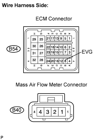
Disconnect the B54 ECM connector.
-
Disconnect the B40 mass air flow meter connector.
-
Measure the resistance according to the value(s) in the table below.
Standard resistance Check for open Tester Connection Specified Condition EVG (B54-8) - Mass air flow meter (B40-2) Below 1 Ω Check for short Tester Connection Specified Condition EVG (B54-8) or Mass air flow meter (B40-2) - Body ground 10 kΩ or higher
NG
REPAIR OR REPLACE HARNESS OR CONNECTOR
OK
-
-
CHECK POWER SOURCE CIRCUIT
-
Check that the battery voltage, ECM power source voltage, and the ground condition of the ECM are normal.
OK The battery voltage, ECM power source voltage, and the ground condition of the ECM are normal. Tech Tips
Make sure that the battery is not discharged during the inspection.
NG
REPAIR POWER SOURCE CIRCUIT
OK
REPLACE ECM
-