ECD SYSTEM, Diagnostic DTC:P0096, P0097, P0098

| DTC Code | DTC Name |
|---|---|
| P0096 | Turbocharged Air Temperature Sensor Gradient Test |
| P0097 | Short to GND in Turbocharged Air Temperature Sensor Circuit |
| P0098 | Open or Short to B+ in Turbocharged Air Temperature Sensor Circuit |
DESCRIPTION
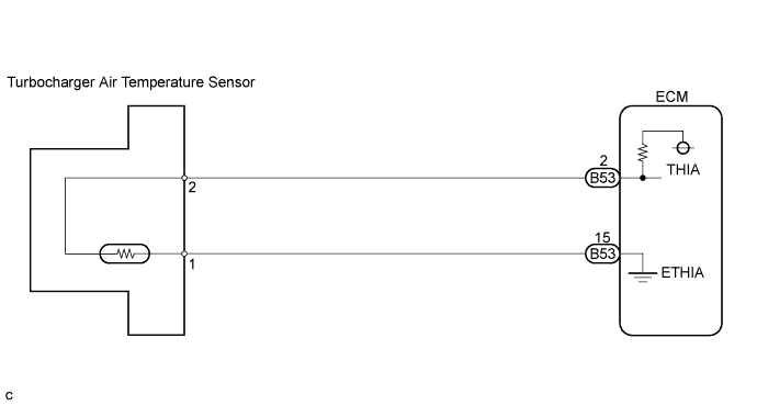
The turbocharger air temperature sensor is installed on the resonator hose. This sensor detects the temperature of the intake air passing through the resonator hose, and sends this signal to the ECM.
When the turbocharger air temperature is low, the resistance in the thermistor increases. When the turbocharger air temperature is high, the resistance drops. The variations in the resistance are reflected as voltage change at the ECM terminal.
Based on this signal, the ECM increases the fuel injection volume to improve the drivability while the engine is cold.
| DTC No. | DTC Detection Condition | Trouble Area | Possible to Detect | |
|---|---|---|---|---|
| Ignition Switch | Engine Run | |||
| P0096 | The output voltage from the turbocharger air temperature sensor suddenly changes for 1.5 sec. or more. (3 trip detection logic) |
|
ON | ON |
| P0097 | The output voltage from the turbocharger air temperature sensor remains less than 0.1 V for 10 sec. or more. (3 trip detection logic) |
|
ON | ON |
| P0098 | The output voltage from the turbocharger air temperature sensor remains more than 4.95 V for 10 sec. or more. (3 trip detection logic) |
|
ON | ON |
FAIL-SAFE
| DTC No. | Fail-safe Operation | Fail-safe Deactivation Condition |
|---|---|---|
| P0096 | A value of 40°C (104°F) for turbocharger is used for ECM control. | Normal condition is restored. |
| P0097 | A value of 40°C (104°F) for turbocharger is used for ECM control. | Normal condition is restored. |
| P0098 | A value of 40°C (104°F) for turbocharger is used for ECM control. | Normal condition is restored. |
WIRING DIAGRAM
INSPECTION PROCEDURE
Tech Tips
-
f the ECM is replaced, variant coding (variant coding indicates the presence of vehicle accessory items, A/C, etc.) should always be performed Click here.
-
Before removing the ECM and the peripheral parts, wait at least 3 minute after turning the ignition switch off (If the cooling fan is operating, remove the ECM and the peripheral parts after the fan stops.).
PROCEDURE
-
CHECK TURBOCHARGER AIR TEMPERATURE SENSOR
-
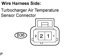
Disconnect the B36 turbocharger air temperature sensor connector.
-
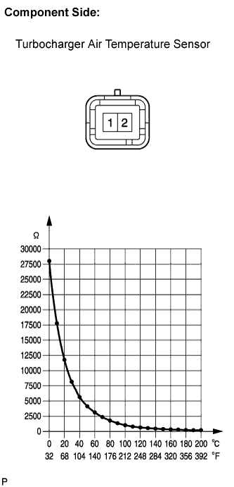
Measure the resistance according to the value(s) in the table below.
Standard resistance Tester Connection Specified Condition 1 - 2 The resistance value is within the acceptable range shown in the illustration. Tech Tips
Refer to the table below.
Turbocharger air temperature
(°C (°F))
Resistance (Ω) 0 (32) 25,000 to 31,000 20 (68) 10,000 to 14,000 40 (104) 5,200 to 6,400 60 (140) 2,600 to 3,300
NG 
REPLACE TURBOCHARGER AIR TEMPERATURE SENSOR
OK 
-
-
INSPECT ECM (VOLTAGE)
-
Disconnect the B36 turbocharger air temperature sensor connector.
-
Turn the ignition switch to the ON position.
-
Measure the voltage according to the value(s) in the table below.
Standard voltage Tester Connection Specified Condition Turbocharger air temperature sensor (B36-2) - Body ground 4.7 to 5.3 V
NG 
CHECK HARNESS AND CONNECTOR (TURBOCHARGER AIR TEMPERATURE SENSOR - ECM) Click here
OK
-
-
CHECK HARNESS AND CONNECTOR (TURBOCHARGER AIR TEMPERATURE SENSOR - ECM)
-
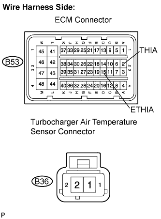
Disconnect the B53 ECM connector.
-
Disconnect the B36 turbocharger air temperature sensor connector.
-
Measure the resistance according to the value(s) in the table below.
Standard resistance Check for open Tester Connection Specified Condition ETHIA (B53-15) - Turbocharger air temperature sensor (B36-1) Below 1 Ω Check for short Tester Connection Specified Condition ETHIA (B53-15) or Turbocharger air temperature sensor (B36-1) - Body ground 10 kΩ or higher
NG
REPAIR OR REPLACE HARNESS OR CONNECTOR
OK
-
-
REPLACE TURBOCHARGER AIR TEMPERATURE SENSOR
NEXT
-
CHECK IF DTC RECURS (P0096, P0097 AND/OR P0098)
-
Connect the intelligent tester to the DLC3.
-
Clear the DTC Click here.
-
Turn the ignition switch on and wait for 10 sec.
-
Turn the intelligent tester on.
-
Select the following menu items: Powertrain / Engine and ECT / DTC.
-
Read the DTCs displayed on the intelligent tester.
Result Display (DTC output) Proceed To No output A P0096, P0097 and/or P0098 B
B
REPLACE ECM
A 
END
-
-
CHECK HARNESS AND CONNECTOR (TURBOCHARGER AIR TEMPERATURE SENSOR - ECM)
-
Disconnect the B53 ECM connector.
-
Disconnect the B36 turbocharger temperature sensor connector.
-
Measure the resistance according to the value(s) in the table below.
Standard resistance Check for open Tester Connection Specified Condition THIA (B53-2) - Turbocharger air temperature sensor (B36-2) Below 1 Ω Check for short Tester Connection Specified Condition THIA (B53-2) or Turbocharger air temperature sensor (B36-2) - Body ground 10 kΩ or higher
NG
REPAIR OR REPLACE HARNESS OR CONNECTOR
OK
-
-
CHECK POWER SOURCE CIRCUIT
-
Check that the battery voltage, ECM power source voltage, and the ground condition of the ECM are normal.
OK The battery voltage, ECM power source voltage, and the ground condition of the ECM are normal. Tech Tips
Make sure that the battery is not discharged during the inspection.
NG
REPAIR POWER SOURCE CIRCUIT
OK
REPLACE ECM
-