ECD SYSTEM DIAGNOSIS SYSTEM

-
DESCRIPTION
-
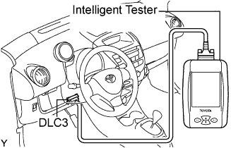
When troubleshooting a Euro-OBD (On-Board Diagnostic) vehicle, an intelligent tester or OBD scan tool must be connected to the DLC3 (Data Link Connector 3) of the vehicle. Various data in the vehicle's ECM (Engine Control Module) can be then read.
-

Euro-OBD regulations require that the vehicle's on-board computer illuminates the MIL (Malfunction Indicator Lamp) in the instrument panel when the computer detects a malfunction in:
-
The emission control system and components.
-
The power train control components (which affect vehicle emissions).
-
The computer itself.
If the malfunction does not recur in 3 consecutive trips, the MIL turns off automatically but the DTCs remain recorded in the ECM memory.
-
-
To check the DTCs, connect an intelligent tester to the DLC3. The tester displays DTCs, freeze frame data, and variety of engine data. The DTCs and freeze frame data can be cleared with the tester (refer to DTC CHECK/CLEAR Click here.
-
-
NORMAL MODE
The diagnosis system operates in normal mode during normal vehicle use. In normal mode, 2 trip detection logic is used to ensure accurate detection of malfunctions.
-
2 TRIP DETECTION LOGIC
When a malfunction is first detected, the malfunction is temporarily stored in the ECM memory (1st trip). If the same malfunction is detected during the next drive cycle, the MIL is illuminated (2nd trip).
-
FREEZE FRAME DATA
The freeze frame data records the engine condition information (fuel system, calculated engine load, engine coolant temperature, fuel trim, engine speed, vehicle speed, etc) as freeze frame data the moment a DTC is stored. When troubleshooting, the freeze frame data can help determine if the vehicle was moving or stationary, if the engine was warmed up or not, if the air-fuel ratio was lean or rich, and other data, from the time the malfunction occurred.
-
DLC3 (Data Link Connector 3)
-
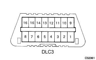
The vehicle's ECM uses the communication protocol. The terminal arrangement of the DLC3 complies and matches the format.
Symbol Terminal No. Name Reference Terminal Result Condition SIL 7 Bus "+" line 5 - Signal ground Pulse generation During transmission CG 4 Chassis ground Body ground 1 Ω or less Always SG 5 Signal ground Body ground 1 Ω or less Always BAT 16 Battery positive Body ground 9 to 14 V Always Tech Tips
The DLC3 is the interface prepared for reading various data from the vehicle's ECM. After connecting the cable of an intelligent tester, turn the ignition switch to the ON position and turn the tester on.
If a communication error message, NO INFORMATION AVAILABLE, is displayed on the tester, and the bus check also failed, a problem exists in either the vehicle or tester. In order to identify the location of the problem, connect the tester to another vehicle.
-
If communication is normal: Inspect the DLC3 on the original vehicle.
-
If communication is impossible: The trouble is probably in the tester itself. Consult the Service Department listed in the tester's instruction manual.
-
-
-
BATTERY VOLTAGE
If the voltage is below 11 V, recharge the battery before proceeding.
-
MIL (Malfunction Indicator Lamp)
-
The MIL illuminates when the ignition switch is turned to the ON position and the engine is not running.
Tech Tips
If the MIL is not illuminated, check the MIL circuit (refer to MIL CIRCUIT Click here.
-
The MIL should turn off when the engine is started. If the MIL remains illuminated, the diagnosis system has detected a malfunction or abnormality in the system.
-