ECD SYSTEM, Diagnostic DTC:P0500, P0501, P1630

| DTC Code | DTC Name |
|---|---|
| P0500 | Vehicle Speed Over-speed |
| P0501 | Vehicle Speed Plausibility Test |
| P1630 | Vehicle Speed not Plausible |
DESCRIPTION
The speed sensor detects the wheel speed and sends appropriate signals to the skid control ECU with actuator. The skid control ECU with actuator converts these wheel speed signals and outputs to the ECM. The ECM determines the vehicle speed based on the frequency of this pulse signal.
| DTC No. | DTC Detection Condition | Trouble Area | Possible to Detect | |
|---|---|---|---|---|
| Ignition Switch | Engine Run | |||
| P0500 | Speed signal is more than 220 km/h (136.7 mph) to the ECM for 5 sec. or more (3 trip detection logic) |
|
- | - |
| P0501 | When driving the vehicle, speed signal is not input to the ECM for 5 sec. or more (3 trip detection logic) |
|
- | - |
| P1630 | Vehicle speed is not plausible for 2 sec. or more. (1 trip detection logic) |
|
- | - |
FAIL-SAFE
| DTC No. | Fail-safe Operation | Fail-safe Deactivation Condition |
|---|---|---|
| P0500 | - | - |
| P0501 | - | - |
| P1630 | - | - |
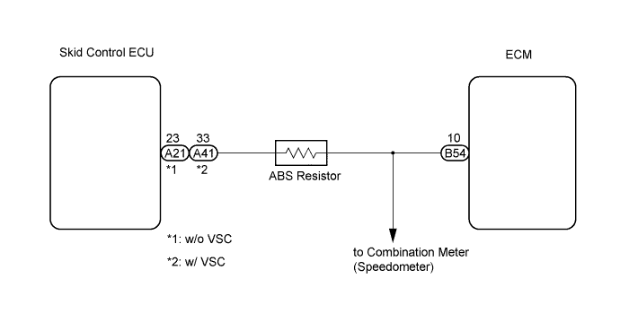
WIRING DIAGRAM
INSPECTION PROCEDURE
Tech Tips
-
When DTC P0500 or P0501 is detected, check the vehicle speed by selecting the following menu items on the intelligent tester: Powertrain / Engine and ECT / Data List / Vehicle Spd.
-
If the ECM is replaced, variant coding (variant coding indicates the presence of vehicle accessory items, A/C, etc.) should always be performed Click here.
-
Before removing the ECM and the peripheral parts, wait at least 3 minute after turning the ignition switch off (If the cooling fan is operating, remove the ECM and the peripheral parts after the fan stops.).
-
The vehicles equipped with the ABS resistor have a resistor on the wire between the ECM and the skid control ECU (see WIRING DIAGRAM).
PROCEDURE
-
READ VALUE OF INTELLIGENT TESTER (VEHICLE SPEED)
-
Connect the intelligent tester to the DLC3.
-
Start the engine and turn the intelligent tester on.
-
Select the following menu items: Powertrain / Engine and ECT / Vehicle Spd.
-
Drive the vehicle.
-
Read the value.
OK The speed displayed on the tester and the actual vehicle speed are almost the same.
NG 
CHECK SPEEDOMETER (OPERATION OF SPEEDOMETER) Click here
OK 
CHECK FOR INTERMITTENT PROBLEMS
-
-
CHECK SPEEDOMETER (OPERATION OF SPEEDOMETER)
-
Drive the vehicle and check if the operation of the speedometer in the combination meter is normal.
Tech Tips
-
The vehicle speed sensor is operating normally if the speedometer reading is normal.
-
If the speedometer reading is abnormal, refer to the speedometer circuit inspection procedure Click here.
-
NG 
CHECK SPEEDOMETER CIRCUIT
OK 
-
-
CHECK HARNESS AND CONNECTOR (SKID CONTROL ECU - ECM)
-
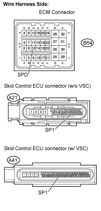
Disconnect the B54 ECM connector.
-
Disconnect the A21 or A41 skid control ECU connector.
-
Measure the resistance according to the value(s) in the table below.
Tech Tips
When checking for open circuit, the wire resistance between connectors indicates a value including the resistance of the ABS resistor.
Standard resistance (Check for open) Tester Connection Specified Condition w/o VSC
SPD (B54-10) - SP1 (A21-23)
19 to 22 Ω w/ VSC
SPD (B54-10) - SP1 (A41-33)
19 to 22 Ω Standard resistance (Check for short) Tester Connection Specified Condition w/o VSC
SPD (B54-10) or SP1 (A21-23) - Body ground
10 kΩ or higher w/ VSC
SPD (B54-10) or SP1 (A41-33) - Body ground
10 kΩ or higher -
Reconnect the ECM connector.
-
Reconnect the skid control ECU connector.
NG
REPAIR OR REPLACE HARNESS OR CONNECTOR
OK
REPLACE ECM
-