ECD SYSTEM, Diagnostic DTC:P0495, P0691, P0692, P0693, P0694

| DTC Code | DTC Name |
|---|---|
| P0495 | FAN Consistency Test |
| P0691 | Short to B+ in FAN1 Circuit |
| P0692 | Open or Short to GND in FAN1 Circuit |
| P0693 | Short to B+ in FAN2 Circuit |
| P0694 | Open or Short to GND in FAN2 Circuit |
DESCRIPTION
-
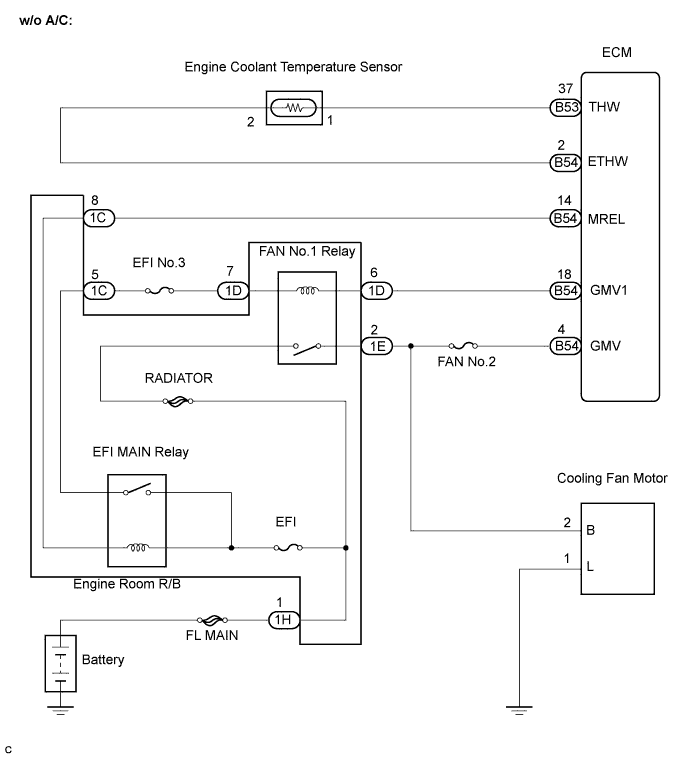
w/o air conditioner:
-
On the models without an air conditioner, the ECM controls the operation of the cooling fan based on engine coolant temperature sensor signals.
-
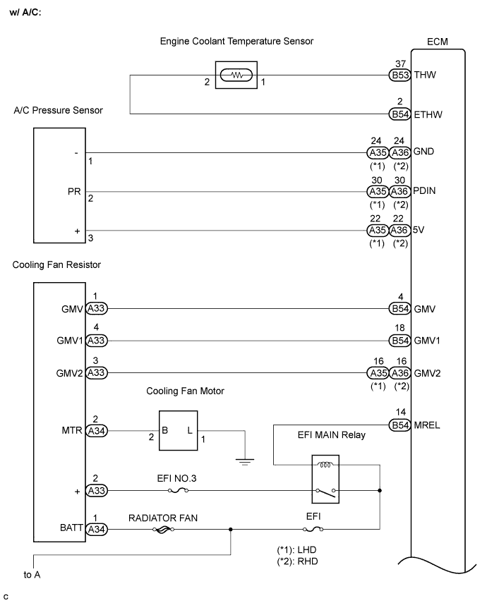
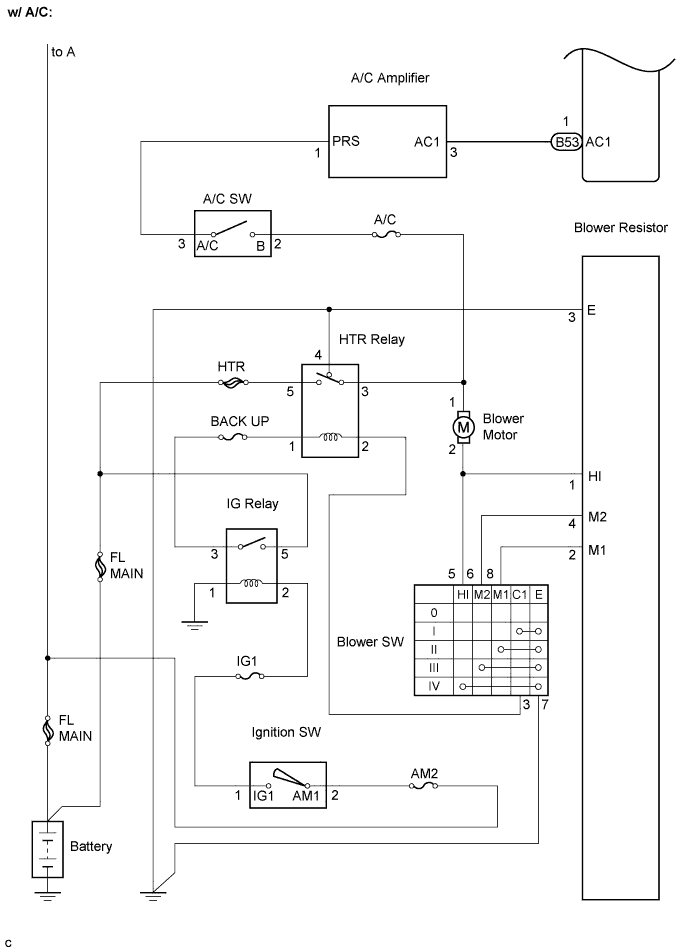
w/ air conditioner:
-
On the models with an air conditioner, the ECM controls the operation of the cooling fan in two speeds (Lo and Hi) based on engine coolant temperature sensor signals and A/C pressure sensor output.
| DTC No. | DTC Detection Condition | Trouble Area | Possible to Detect | |
|---|---|---|---|---|
| Ignition Switch | Engine Run | |||
| P0495 | Consistency between calculated speed and actual speed is not detected. |
|
ON | ON |
| P0691 | Short in fan 1 circuit (Power supply side) for 5 sec. or more. |
|
ON | ON |
| P0692 | Open or short in fan 1 circuit for 5 sec. or more. |
|
ON | ON |
| P0693 | Short in fan 2 circuit (Power supply side) for 5 sec. or more. |
|
ON | ON |
| P0694 | Open or short in fan 2 circuit for 5 sec. or more. |
|
ON | ON |
Tech Tips
| Engine coolant temperature | Less than 97°C (206.6°F) | 97°C (206.6°F) or higher |
|---|---|---|
| Cooling fan operation | OFF | ON |
| Air conditioning condition | Engine coolant temperature | ||
|---|---|---|---|
| Compressor | Refrigerant Pressure | 97 to 105°C (206.6 to 221°F) | 105°C (221°F) or more |
| OFF | - | Low speed | High speed |
| ON | Low pressure | Low speed | High speed |
| High pressure | High speed | High speed | |
-
When engine coolant temperature is 115°C (239°F) or more, the operation of the air conditioner compressor is stopped.
-
When engine coolant temperature is more than 118°C (244.4°F), the warning light comes on.
FAIL-SAFE
| DTC No. | Fail-safe Operation | Fail-safe Deactivation Condition |
|---|---|---|
| P0495 | Stops the A/C. | Normal condition is restored. |
| P0691 | Stops the A/C. | Normal condition is restored. |
| P0692 | Stops the A/C. | Normal condition is restored. |
| P0693 | Stops the A/C. | Normal condition is restored. |
| P0694 | Stops the A/C. | Normal condition is restored. |
WIRING DIAGRAM
INSPECTION PROCEDURE
Tech Tips
-
If the ECM is replaced, variant coding (variant coding indicates the presence of vehicle accessory items, A/C, etc.) should always be performed Click here.
-
Before removing the ECM and the peripheral parts, wait at least 3 minute after turning the ignition switch off (If the cooling fan is operating, remove the ECM and the peripheral parts after the fan stops.).
PROCEDURE
-
CHECK IF VEHICLE IS EQUIPPED WITH A/C
-
Check if the vehicle is equipped with the A/C.
Result Result Proceed To w/o A/C A w/ A/C B
B 
PERFORM ACTIVE TEST BY INTELLIGENT TESTER (OPERATE FAN) Click here
A 
-
-
PERFORM ACTIVE TEST BY INTELLIGENT TESTER (OPERATE FAN)
-
Connect the intelligent tester to the DLC3.
-
Turn the ignition switch to the ON position and turn the intelligent tester on.
-
Clear the DTC Click here.
-
Select the following menu items: Powertrain / Engine and ECT / Active Test / Fan 1.
-
Check the operation of the fan while operating it using the intelligent tester.
Standard Fan active test Condition Activated Fan operates Deactivated Fan stops Tech Tips
To check if a voltage is applied to the cooling fan, select the following menu items: Powertrain / Engine and ECT / Data List / Fan Relay.
NG
INSPECT ENGINE ROOM R/B (VOLTAGE) Click here
OK 
CHECK FOR INTERMITTENT PROBLEMS
-
-
INSPECT ENGINE ROOM R/B (VOLTAGE)
-
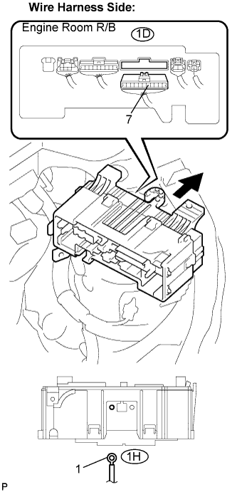
Remove the engine room R/B.
-
Remove the engine room R/B lower cover.
-
Disconnect the 1D and 1H engine room R/B connectors.
-
Turn the ignition switch to the ON position.
-
Measure the voltage according to the value(s) in the table below.
Standard voltage Tester Connection Specified Condition Engine room R/B (1D-7) - Body ground 11 to 14 V Engine room R/B (1H-1) - Body ground 11 to 14 V
NG 
CHECK AND REPAIR HARNESS AND CONNECTOR (BATTERY - ENGINE ROOM R/B)
OK
-
-
CHECK HARNESS AND CONNECTOR (ENGINE ROOM R/B - ECM)
-
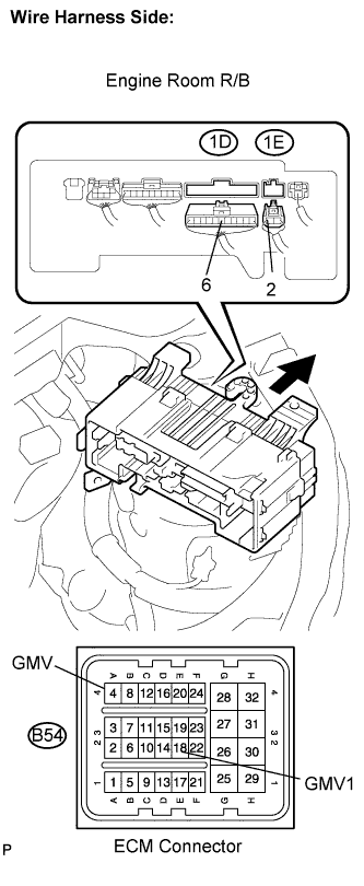
Disconnect the B54 ECM connector.
-
Remove the engine room R/B.
-
Remove the engine room R/B lower cover.
-
Disconnect the 1D and 1E engine room R/B connectors.
-
Measure the resistance according to the value(s) in the table below.
Standard resistance Check for open Tester Connection Specified Condition GMV (B54-4) - Engine room R/B (1E-2) Below 1 Ω GMV1 (B54-18) - Engine room R/B (1D-6) Below 1 Ω Check for short Tester Connection Specified Condition GMV (B54-4) or Engine room R/B (1E-2) - Body ground 10 kΩ or higher GMV1 (B54-18) or Engine room R/B (1D-6) - Body ground 10 kΩ or higher
NG
REPAIR OR REPLACE HARNESS OR CONNECTOR
OK
-
-
REPLACE ENGINE ROOM R/B (FAN NO.1 RELAY)
NEXT
-
PERFORM ACTIVE TEST BY INTELLIGENT TESTER (OPERATE FAN)
-
Connect the intelligent tester to the DLC3.
-
Turn the ignition switch to the ON position and turn the intelligent tester on.
-
Clear the DTC Click here.
-
Select the following menu items: Powertrain / Engine and ECT / Active Test / Fan 1.
-
Check the operation of the fan while operating it using the intelligent tester.
Standard Fan active test Condition Activated Fan operates Deactivated Fan stops Tech Tips
To check if a voltage is applied to the cooling fan, select the following menu items: Powertrain / Engine and ECT / Data List / Fan Relay.
NG
REPLACE ECM
OK
END
-
-
PERFORM ACTIVE TEST BY INTELLIGENT TESTER (OPERATE FAN)
-
Connect the intelligent tester to the DLC3.
-
Turn the ignition switch to the ON position and turn the intelligent tester on.
-
Clear the DTC Click here.
-
Select the following menu items: Powertrain / Engine and ECT / Active Test / Fan 1 and Fan 2.
-
Check the operation of the fan while operating it using the intelligent tester.
Standard Fan active test Condition Deactivated Fan stops Activated (Fan 1) Fan operates Activated (Fan 2) Fan operates
NG
CHECK HARNESS AND CONNECTOR (COOLING FAN RESISTOR - COOLING FAN MOTOR) Click here
OK
CHECK FOR INTERMITTENT PROBLEMS
-
-
CHECK HARNESS AND CONNECTOR (COOLING FAN RESISTOR - COOLING FAN MOTOR)
-
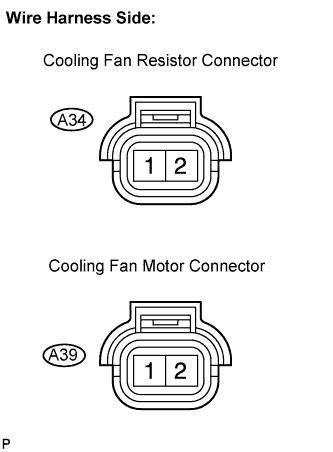
Disconnect the A34 cooling fan resistor connector.
-
Disconnect the A39 cooling fan motor connector.
-
Measure the resistance according to the value(s) in the table below.
Standard resistance Check for open Tester Connection Specified Condition Cooling fan resistor (A34-2) - Cooling fan motor (A39-2) Below 1 Ω Check for short Tester Connection Specified Condition Cooling fan resistor (A34-2) or Cooling fan motor (A39-2) - Body ground 10 kΩ or higher
NG
REPAIR OR REPLACE HARNESS OR CONNECTOR
OK
-
-
INSPECT COOLING FAN RESISTOR (VOLTAGE)
-
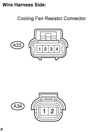
Disconnect the A33 and A34 cooling fan resistor connectors.
-
Turn the ignition switch to the ON position.
-
Measure the voltage according to the value(s) in the table below.
Standard voltage Tester Connection Specified Condition Cooling fan resistor (A33-2) - Body ground 11 to 14 V Cooling fan resistor (A34-1) - Body ground 11 to 14 V
NG
CHECK AND REPAIR HARNESS AND CONNECTOR (BATTERY - COOLING FAN RESISTOR)
OK
-
-
CHECK HARNESS AND CONNECTOR (COOLING FAN RESISTOR - ECM)
-
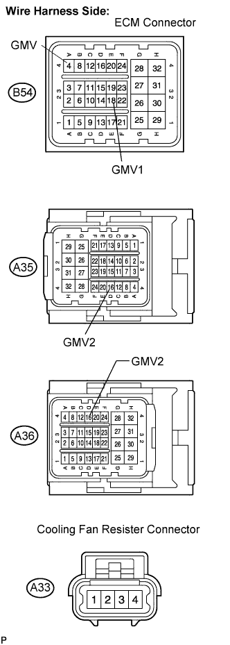
Disconnect the A35 (A36) and B54 ECM connectors.
-
Disconnect the A33 cooling fan resistor connector.
-
Measure the resistance according to the value(s) in the table below.
Standard resistance (Check for open) LHD Tester Connection Specified Condition GMV (B54-4) - Cooling fan resistor (A33-1) Below 1 Ω GMV1 (B54-18) - Cooling fan resistor (A33-4) Below 1 Ω GMV2 (A35-16) - Cooling fan resistor (A33-3) Below 1 Ω RHD Tester Connection Specified Condition GMV (B54-4) - Cooling fan resistor (A33-1) Below 1 Ω GMV1 (B54-18) - Cooling fan resistor (A33-4) Below 1 Ω GMV2 (A36-16) - Cooling fan resistor (A33-3) Below 1 Ω Standard resistance (Check for short) LHD Tester Connection Specified Condition GMV (B54-4) or Cooling fan resistor (A33-1) - Body ground 10 kΩ or higher GMV1 (B54-18) or Cooling fan resistor (A33-4) - Body ground 10 kΩ or higher GMV2 (A35-16) or Cooling fan resistor (A33-3) - Body ground 10 kΩ or higher RHD Tester Connection Specified Condition GMV (B54-4) or Cooling fan resistor (A33-1) - Body ground 10 kΩ or higher GMV1 (B54-18) or Cooling fan resistor (A33-4) - Body ground 10 kΩ or higher GMV2 (A36-16) or Cooling fan resistor (A33-3) - Body ground 10 kΩ or higher
NG
REPAIR OR REPLACE HARNESS OR CONNECTOR
OK
-
-
REPLACE COOLING FAN RESISTOR
NEXT
-
PERFORM ACTIVE TEST BY INTELLIGENT TESTER (OPERATE FAN)
-
Connect the intelligent tester to the DLC3.
-
Turn the ignition switch to the ON position and turn the intelligent tester on.
-
Clear the DTC Click here.
-
Select the following menu items: Powertrain / Engine and ECT / Active Test / Fan 1 and Fan 2.
-
Check the operation of the fan while operating it using the intelligent tester.
Standard Fan active test Condition Deactivated Fan stops Activated (Fan 1) Fan operates Activated (Fan 2) Fan operates
NG
REPLACE ECM
OK
END
-