ECD SYSTEM, Diagnostic DTC:P0341, P0343

| DTC Code | DTC Name |
|---|---|
| P0341 | Open, Short or No Signal in Camshaft Position Sensor Circuit |
| P0343 | Camshaft Position Sensor Range / Performance |
DESCRIPTION
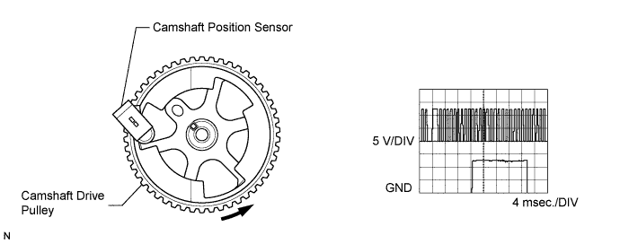
The camshaft position sensor is installed on the camshaft housing. It is a Hall-effect type sensor. When the signal-detecting portion on the camshaft drive pulley passes in front of the camshaft position sensor, the air gap between the sensor and the signal-detecting position changes. The camshaft position sensor converts this change into a signal and sends it to the ECM.
The ECM needs a cylinder reference in order to phase the injection actuation in sequential mode (cylinder by cylinder, in the 1-3-4-2 order).
| DTC No. | DTC Detection Condition | Trouble Area | Possible to Detect | |
|---|---|---|---|---|
| Ignition Switch | Engine Run | |||
| P0341 | Either the following conditions (a) or (b) is met: (a) No camshaft position sensor signal. (b) Open or short circuit in camshaft position sensor circuit. |
|
ON | ON |
| P0343 | Changes in the camshaft position sensor signal level take place outside the calibrated windows (Badly position in relation to the crankshaft position sensor signal.). |
|
ON | ON |
-
Reference:
-
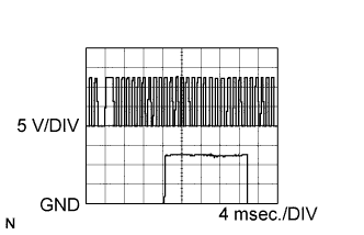
The waveform between terminals G+ and G- of the ECM connectors with the engine idling.
FAIL-SAFE
| DTC No. | Fail-safe Operation | Fail-safe Deactivation Condition |
|---|---|---|
| P0341 | Difficult to start. | Ignition switch OFF. |
| P0343 | Difficult to start. | Ignition switch OFF. |
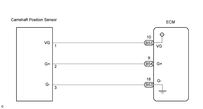
WIRING DIAGRAM
INSPECTION PROCEDURE
Tech Tips
-
When DTC P0341 or P0343 is detected and the engine is started, check the synchronization between camshaft and the crankshaft by selecting the following menu items on the intelligent tester: Powertrain / Engine and ECT / Data List / Synchro Cam-Crank.
-
If the ECM is replaced, variant coding (variant coding indicates the presence of vehicle accessory items, A/C, etc.) should always be performed Click here.
-
Before removing the ECM and the peripheral parts, wait at least 3 minute after turning the ignition switch off (If the cooling fan is operating, remove the ECM and the peripheral parts after the fan stops.).
PROCEDURE
-
CHECK DTC OUTPUT (OTHER THAN P0341AND/OR P0343)
-
Connect the intelligent tester to the DLC3.
-
Turn the ignition switch to the ON position and turn the intelligent tester on.
-
Select the following menu items: Powertrain / Engine and ECT / DTC.
-
Read the DTCs.
Result Display (DTC output) Proceed To P0341 and/or P0343 A P0341, P0343 and other DTCs B Tech Tips
If any other codes besides P0341 and P0343 are output, perform the troubleshooting for those DTCs first.
B 
GO TO DTC CHART
A 
-
-
CHECK IF ENGINE STARTS
Result Display (DTC output) Proceed To Engine starts. A Engine does not start. B
B 
INSPECT ECM Click here
A
-
READ VALUE OF INTELLIGENT TESTER (SYNCHRONIZATION CAMSHAFT - CRANKSHAFT)
-
Connect the intelligent tester to the DLC3.
-
Start the engine and turn the intelligent tester on.
-
Select the following menu items: Powertrain / Engine and ECT / Synchronization Cam-Crank.
-
Read the value.
Result Display (DTC output) Proceed To ON A OFF B
NG
INSPECT ECM Click here
OK 
CHECK FOR INTERMITTENT PROBLEMS
-
-
INSPECT ECM
-
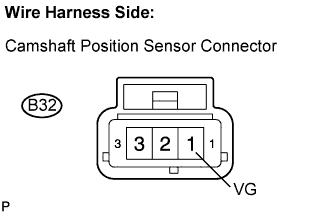
Disconnect the B32 camshaft position sensor connector.
-
Turn the ignition switch to the ON position.
-
Measure the voltage according to the value(s) in the table below.
Standard voltage Tester Connection Specified Condition VG (B32-1) - Body ground 4.5 to 5.5 V
NG
CHECK HARNESS AND CONNECTOR (CAMSHAFT POSITION SENSOR - ECM) Click here
OK
-
-
CHECK HARNESS AND CONNECTOR (CAMSHAFT POSITION SENSOR - ECM)
-
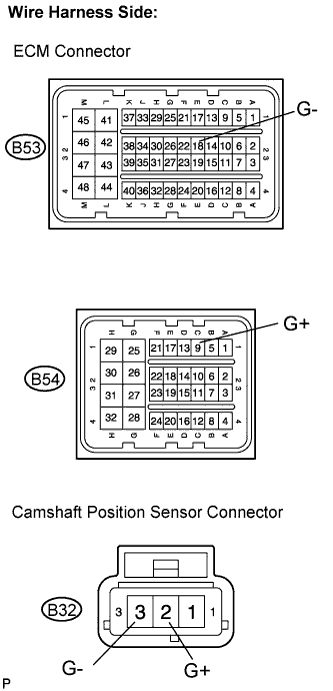
Disconnect the B53 and B54 ECM connectors.
-
Disconnect the B32 camshaft position sensor connector.
-
Measure the resistance according to the value(s) in the table below.
Standard resistance Check for open Tester Connection Specified Condition G+ (B54-9) - G+ (B32-2) Below 1 Ω G- (B53-18) - G- (B32-3) Below 1 Ω Check for short Tester Connection Specified Condition G+ (B54-9) or G+ (B32-2) - Body ground 10 kΩ or higher G- (B53-18) or G- (B32-3) - Body ground 10 kΩ or higher
NG
REPAIR OR REPLACE HARNESS OR CONNECTOR
OK
-
-
CHECK SENSOR INSTALLATION (CAMSHAFT POSITION SENSOR)
-
Check the installation condition of the camshaft position sensor.
OK The sensor is installed correctly.
NG
REPAIR OR REPLACE CAMSHAFT POSITION SENSOR
OK
-
-
CHECK SENSOR AIRGAP (CAMSHAFT POSITION SENSOR)
-
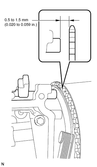
Measure the camshaft position sensor airgap.
Standard 0.5 to 1.5 mm (0.020 to 0.059 in.)
NG
REPAIR OR REPLACE CAMSHAFT POSITION SENSOR
OK
-
-
INSPECT CAMSHAFT DRIVE PULLEY
-
Check the camshaft drive pulley.
OK The camshaft drive pulley does not have any cracks or deformation.
NG
REPLACE CAMSHAFT DRIVE PULLEY
OK
-
-
CHECK POWER SOURCE CIRCUIT
-
Check that the battery voltage, ECM power source voltage, and the ground condition of the ECM are normal.
OK The battery voltage, ECM power source voltage, and the ground condition of the ECM are normal. Tech Tips
Make sure that the battery is not discharged during the inspection.
NG
REPAIR POWER SOURCE CIRCUIT
OK
-
-
REPLACE CAMSHAFT POSITION SENSOR
NEXT
-
CHECK IF DTC RECURS (P0341 AND/OR P0343)
-
Connect the intelligent tester to the DLC3.
-
Clear the DTC Click here.
-
Turn the ignition switch to the ON position and turn the intelligent tester on.
-
Select the following menu items: Powertrain / Engine and ECT / DTC.
-
Read the DTCs displayed on the intelligent tester.
Result Display (DTC output) Proceed To No output A DTC P0341 and/or P0343 B
B
REPLACE ECM
A
END
-
-
CHECK HARNESS AND CONNECTOR (CAMSHAFT POSITION SENSOR - ECM)
-
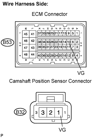
Disconnect the B53 ECM connector.
-
Disconnect the B32 camshaft position sensor connector.
-
Measure the resistance according to the value(s) in the table below.
Standard resistance Check for open Tester Connection Specified Condition VG (B53-10) - VG (B32-1) Below 1 Ω Check for short Tester Connection Specified Condition VG (B53-10) or VG (B32-1) - Body ground 10 kΩ or higher
NG
REPAIR OR REPLACE HARNESS OR CONNECTOR
OK
REPLACE ECM
-