ECD SYSTEM, Diagnostic DTC:P0222, P0223, P0227, P0228, P1627, P2137, P2299

| DTC Code | DTC Name |
|---|---|
| P0222 | Short to GND in Accelerator Pedal Sensor Track 1 Circuit |
| P0223 | Open or Short to B+ in Accelerator Pedal Sensor Track 1 Circuit |
| P0227 | Short to GND in Accelerator Pedal Sensor Track 2 Circuit |
| P0228 | Open or Short to B+ in Accelerator Pedal Sensor Track 2 Circuit |
| P1627 | Pedal Value not Plausible |
| P2137 | Accelerator Pedal Sensor Value Plausibility between the Two Tracks |
| P2299 | Accelerator Pedal Sensor Stick Pedal Detect |
DESCRIPTION
The accelerator pedal position sensor is mounted on the accelerator pedal bracket and has 2 sensors that detect the accelerator position and malfunctions of the accelerator pedal position sensor itself.
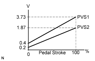
In the accelerator pedal position sensor, the voltage applied to pedal terminals PVS1 and PVS2 of the ECM changes between 0.2 V and 3.73 V in proportion to the opening angle of the accelerator pedal position sensor. The signal sent to PVS1 indicates the accelerator pedal opening angle, and PVS2 output is used for detecting a malfunction in the sensor.
The ECM determines the actual accelerator pedal angle with the signals transmitted from pedal terminals PVS1 and PVS2, and controls the engine based on these signals.
Tech Tips
The output voltage from PVS2 is half of that from PVS1.
| DTC No. | DTC Detection Condition | Trouble Area | Possible to Detect | |
|---|---|---|---|---|
| Ignition Switch | Engine Run | |||
| P0222 | The output voltage from the PVS1 terminal is less than 0.1 V for 0.12 sec. or more. (1 trip detection logic) |
|
ON | ON |
| P0223 | The output voltage from the PVS1 terminal is more than 4.7 V for 0.12 sec. or more. (1 trip detection logic) |
|
ON | ON |
| P0227 | The output voltage from the PVS2 terminal is less than 0.1 V for 0.12 sec. or more. (1 trip detection logic) |
|
ON | ON |
| P0228 | The output voltage from the PVS2 terminal is more than 4.7 V for 0.12 sec. or more. (1 trip detection logic) |
|
ON | ON |
| P1627 | Value plausibility between signal and calculate value is detected for 0.48 sec. or more. |
|
ON | ON |
| P2137 | Value plausibility between PVS1 and PVS2 is detected for 0.14 sec. or more. (1 trip detection logic) |
|
ON | ON |
| P2299 | The accelerator pedal position sensor remains stuck for 1 sec. or more. (1 trip detection logic) |
|
ON | ON |
-
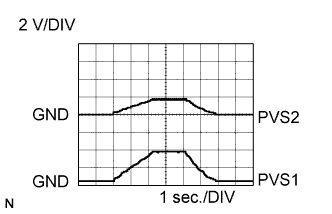
Reference:
-
When the ignition switch ON and the accelerator pedal is released and depressed, the output voltage between terminals PVS1, PVS2 and SS2E of ECM connectors.
FAIL-SAFE
| DTC No. | Fail-safe Operation | Fail-safe Deactivation Condition |
|---|---|---|
| P0222 | Limits the engine power. | Ignition switch OFF. |
| P0223 | Limits the engine power. | Ignition switch OFF. |
| P0227 | Limits the engine power. | Ignition switch OFF. |
| P0228 | Limits the engine power. | Ignition switch OFF. |
| P1627 | Limits the engine speed (2,000 rpm). | Ignition switch OFF. |
| P2137 | Limits the engine power. | Ignition switch OFF. |
| P2299 | The specified value is used as the idle speed. | - |
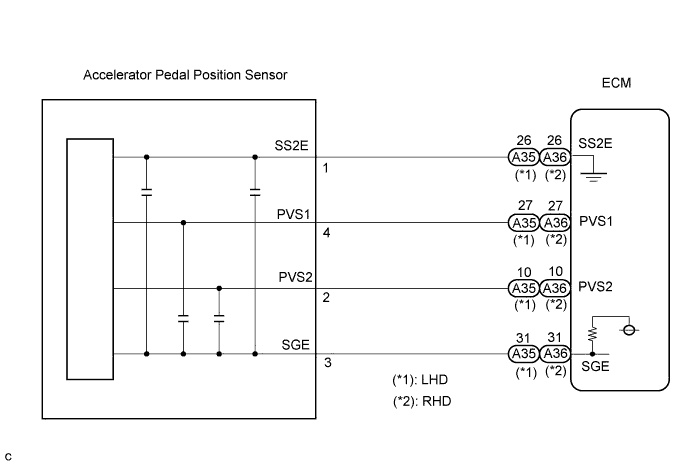
WIRING DIAGRAM
INSPECTION PROCEDURE
Tech Tips
-
When DTC P0222, P0223, P0227 or P0228 is detected, check the accelerator pedal position sensor output voltage by selecting the following menu items on the intelligent tester: Powertrain / Engine and ECT / Data List / Accel Pos.
-
If only DTC P2137 is output, replace the accelerator pedal position sensor.
-
If only DTC P2299 is output, replace the accelerator pedal position sensor.
-
If the ECM is replaced, variant coding (variant coding indicates the presence of vehicle accessory items, A/C, etc.) should always be performed Click here.
-
Before removing the ECM and the peripheral parts, wait at least 3 minute after turning the ignition switch off (If the cooling fan is operating, remove the ECM and the peripheral parts after the fan stops.).
PROCEDURE
-
READ VALUE OF INTELLIGENT TESTER (ACCELERATOR PEDAL POSITION SENSOR VOLTAGE)
-
Connect the intelligent tester to the DLC3.
-
Turn the ignition switch to the ON position and turn the intelligent tester on.
-
Select the following menu items: Powertrain / Engine and ECT / Accel Pos.
-
Read the value.
Result Condition Specified Condition Gradually release the accelerator pedal with it fully released. Smooth change from 0 to 100%.
NG 
CHECK HARNESS AND CONNECTOR (ACCELERATOR PEDAL POSITION SENSOR - ECM) Click here
OK 
CHECK FOR INTERMITTENT PROBLEMS
-
-
CHECK HARNESS AND CONNECTOR (ACCELERATOR PEDAL POSITION SENSOR - ECM)
-
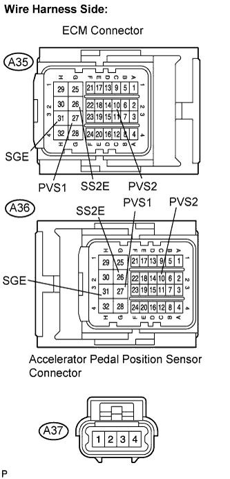
Disconnect the A35 (A36) ECM connector.
-
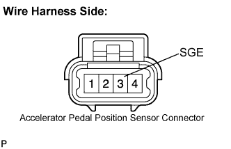
Disconnect the A37 accelerator pedal position sensor connector.
-
Measure the resistance according to the value(s) in the table below.
Standard resistance (Check for open) LHD Tester Connection Specified Condition SGE (A35-31) - SGE (A37-3) Below 1 Ω PVS1 (A35-27) - PVS1 (A37-4) Below 1 Ω PVS2 (A35-10) - PVS2 (A37-2) Below 1 Ω SS2E (A35-26) - SS2E (A37-1) Below 1 Ω RHD Tester Connection Specified Condition SGE (A36-31) - SGE (A37-3) Below 1 Ω PVS1 (A36-27) - PVS1 (A37-4) Below 1 Ω PVS2 (A36-10) - PVS2 (A37-2) Below 1 Ω SS2E (A36-26) - SS2E (A37-1) Below 1 Ω Standard resistance (Check for short) LHD Tester Connection Specified Condition SGE (A35-31) or SGE (A37-3) - Body ground 10 kΩ or higher PVS1 (A35-27) or PVS1 (A37-4) - Body ground 10 kΩ or higher PVS2 (A35-10) or PVS2 (A37-2) - Body ground 10 kΩ or higher SS2E (A35-26) or SS2E (A37-1) - Body ground 10 kΩ or higher RHD Tester Connection Specified Condition SGE (A36-31) or SGE (A37-3) - Body ground 10 kΩ or higher PVS1 (A36-27) or PVS1 (A37-4) - Body ground 10 kΩ or higher PVS2 (A36-10) or PVS2 (A37-2) - Body ground 10 kΩ or higher SS2E (A36-26) or SS2E (A37-1) - Body ground 10 kΩ or higher
NG 
REPAIR OR REPLACE HARNESS OR CONNECTOR
OK 
-
-
INSPECT ECM (VOLTAGE)
-
Disconnect the A37 accelerator pedal position sensor connector.
-
Turn the ignition switch to the ON position.
-
Measure the voltage according to the value(s) in the table below.
Standard voltage Tester Connection Specified Condition SGE (A37-3) - Body ground 4.7 to 5.3 V
NG
CHECK POWER SOURCE CIRCUIT Click here
OK
REPLACE ACCELERATOR PEDAL POSITION SENSOR
-
-
CHECK POWER SOURCE CIRCUIT
-
Check that the battery voltage, ECM power source voltage, and the ground condition of the ECM are normal.
OK The battery voltage, ECM power source voltage, and the ground condition of the ECM are normal. Tech Tips
Make sure that the battery is not discharged during the inspection.
NG
REPAIR POWER SOURCE CIRCUIT
OK
REPLACE ECM
-