ECD SYSTEM, Diagnostic DTC:P0215

| DTC Code | DTC Name |
|---|---|
| P0215 | Open, Short to B+ or Short to GND in Main Relay Circuit |
DESCRIPTION
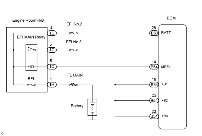
A signal output from the MREL terminal of the ECM causes a current to flow to the coil of the EFI MAIN relay, closing the contact of the EFI MAIN relay and supplying power to +B1, +B2 and +B3 terminals of the ECM.
| DTC No. | DTC Detection Condition | Trouble Area | Possible to Detect | |
|---|---|---|---|---|
| Ignition Switch | Engine Run | |||
| P0215 | Open or short in EFI MAIN relay circuit |
|
ON | ON |
FAIL-SAFE
| DTC No. | Fail-safe Opreation | Fail-safe Deactivation Condition |
|---|---|---|
| P0215 | Engine reaction: engine stall | - |
WIRING DIAGRAM
INSPECTION PROCEDURE
Tech Tips
-
If the ECM is replaced, variant coding (variant coding indicates the presence of vehicle accessory items, A/C, etc.) should always be performed Click here.
-
Before removing the ECM and the peripheral parts, wait at least 3 minute after turning the ignition switch off (If the cooling fan is operating, remove the ECM and the peripheral parts after the fan stops.).
PROCEDURE
-
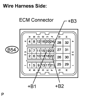
INSPECT ECM (VOLTAGE)
-
Disconnect the B54 ECM connector.
-
Turn the ignition switch to the ON position.
-
Measure the voltage according to the value(s) in the table below.
Standard voltage Tester Connection Specified Condition +B1 (B54-19) - Body ground 11 to 14 V +B2 (B54-22) - Body ground 11 to 14 V +B3 (B54-23) - Body ground 11 to 14 V
NG 
CHECK HARNESS AND CONNECTOR (EFI MAIN RELAY - ECM) Click here
OK 
CHECK FOR INTERMITTENT PROBLEMS
-
-
CHECK HARNESS AND CONNECTOR (EFI MAIN RELAY - ECM)
-
Disconnect the B54 ECM connector.
-
Remove the engine room R/B.
-
Remove the engine room R/B lower cover.
-
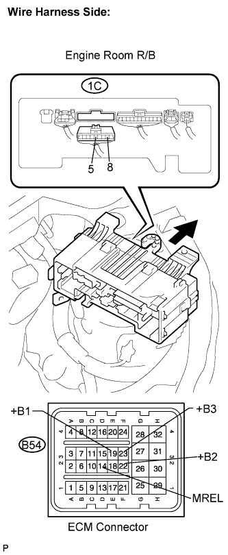
Disconnect the 1C engine room R/B connector.
-
Measure the resistance according to the value(s) in the table below.
Standard resistance Check for open Tester Connection Specified Condition MREL (B54-14) - Engine room R/B (1C-8) Below 1 Ω +B1 (B54-19) - Engine room R/B (1C-5) Below 1 Ω +B2 (B54-22) - Engine room R/B (1C-5) Below 1 Ω +B3 (B54-23) - Engine room R/B (1C-5) Below 1 Ω Check for short Tester Connection Specified Condition MREL (B54-14) or Engine room R/B (1C-8) - Body ground 10 kΩ or higher +B1 (B54-19) or Engine room R/B (1C-5) - Body ground 10 kΩ or higher +B2 (B54-22) or Engine room R/B (1C-5) - Body ground 10 kΩ or higher +B3 (B54-23) or Engine room R/B (1C-5) - Body ground 10 kΩ or higher
NG 
REPAIR OR REPLACE HARNESS OR CONNECTOR
OK 
-
-
INSPECT EFI MAIN RELAY (VOLTAGE)
-
Remove the engine room R/B.
-
Remove the engine room R/B lower cover.
-
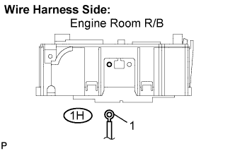
Disconnect the 1H engine room R/B connector.
-
Measure the voltage according to the value(s) in the table below.
Standard voltage Tester Connection Specified Condition Engine room R/B (1H-1) - Body ground 11 to 14 V
NG
CHECK AND REPAIR HARNESS AND CONNECTOR (BATTERY - ENGINE ROOM R/B)
OK
-
-
REPLACE ENGINE ROOM R/B (EFI MAIN RELAY)
NEXT
-
CHECK IF DTC RECURS (P0215)
-
Connect the intelligent tester to the DLC3.
-
Clear the DTC Click here.
-
Turn the ignition switch to the ON position and turn the intelligent tester on.
-
Select the following menu items: Powertrain / Engine and ECT / DTC.
-
Read the DTCs displayed on the intelligent tester.
Result Display (DTC output) Proceed to No output A P0215 B
B
REPLACE ECM
A
END
-