ECD SYSTEM, Diagnostic DTC:P0562, P0563

| DTC Code | DTC Name |
|---|---|
| P0562 | Battery Voltage Value Too Low |
| P0563 | Battery Voltage Value Too High |
DESCRIPTION
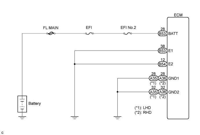
Battery voltage is applied to the BATT terminal regardless of the ignition switch operation. This voltage is used to diagnose the engine control system or to retain learning values or other data.
| DTC No. | DTC Detection Condition | Trouble Area | Possible to Detect | |
|---|---|---|---|---|
| Ignition Switch | Engine Run | |||
| P0562 | The battery voltage remains less than 6.8 V for 2 sec. or more. (3 trip detection logic) |
|
ON | - |
| P0563 | The battery voltage exceeds 18 V for 2 sec. or more. (3 trip detection logic) |
|
ON | - |
FAIL-SAFE
| DTC No. | Fail-safe Operation | Fail-safe Deactivation Condition |
|---|---|---|
| P0562 | - | - |
| P0563 | - | - |
WIRING DIAGRAM
INSPECTION PROCEDURE
Tech Tips
-
When DTC P0562 or P0563 is detected, check the battery voltage by selecting the following menu items on the intelligent tester: Powertrain / Engine and ECT / Data List / Batt.
-
If the ECM is replaced, variant coding (variant coding indicates the presence of vehicle accessory items, A/C, etc.) should always be performed Click here.
-
Before removing the ECM and the peripheral parts, wait at least 3 minute after turning the ignition switch off (If the cooling fan is operating, remove the ECM and the peripheral parts after the fan stops.).
PROCEDURE
-
CHECK DTC OUTPUT (P0562 OR P0563)
-
Connect the intelligent tester to the DLC3.
-
Turn the ignition switch to the ON position and turn the intelligent tester on.
-
Select the following menu items: Powertrain / Engine and ECT / DTC.
-
Read the DTCs.
Result Result Proceed To P0562 A P0563 B
B 
CHECK BATTERY Click here
A 
-
-
CHECK IF ENGINE STARTS
Result Result Proceed To Engine does not start. A Engine starts. B
B
CHECK HARNESS AND CONNECTOR (BATTERY - ECM) Click here
A
-
CHECK BATTERY TERMINAL CABLE INSTALLATION
-
Check the installation condition of the battery terminal cable.
OK The terminal cable is installed correctly.
NG 
REPAIR OR REPLACE BATTERY TERMINAL CABLE
OK
-
-
CHECK BATTERY VOLTAGE
-
Check the battery voltage.
Note
Carry out this check with the engine stopped and the ignition switch off.
Standard Result Proceed To 11 V or more A Below 11 V B
B
CHARGE OR REPLACE BATTERY
A
-
-
CHECK HARNESS AND CONNECTOR (BATTERY - ECM)
-
Disconnect the battery negative terminal cable.
-
Disconnect the battery positive terminal cable.
-
Disconnect the B53 ECM connector.
-
Measure the resistance according to the value(s) in the table below.
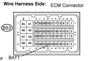
Standard resistance Check for open Tester Connection Specified Condition BATT (B53-28) - Battery positive terminal Below 1 Ω Check for short Tester Connection Specified Condition BATT (B53-28) - Battery positive terminal - Body ground 10 kΩ or higher Note
After reconnection of the battery cable, the radio and clock should be adjusted as they were previously.
NG
REPAIR OR REPLACE HARNESS OR CONNECTOR
OK
-
-
CHECK HARNESS AND CONNECTOR (ECM - BODY GROUND)
-
Disconnect the A35 (A36) ECM connector.
-
Measure the resistance according to the value(s) in the table below.
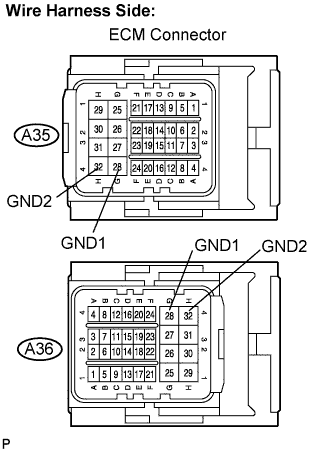
Standard resistance (Check for open) LHD Tester Connection Specified Condition GND1 (A35-28) - Body ground Below 1 Ω GND2 (A35-32) - Body ground Below 1 Ω RHD Tester Connection Specified Condition GND1 (A36-28) - Body ground Below 1 Ω GND2 (A36-32) - Body ground Below 1 Ω
NG
REPAIR OR REPLACE HARNESS OR CONNECTOR
OK
-
-
CHECK HARNESS AND CONNECTOR (ECM - BODY GROUND)
-
Disconnect the B53 and B54 ECM connectors.
-
Measure the resistance according to the value(s) in the table below.
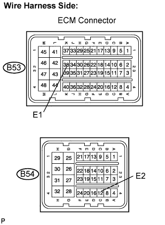
Standard resistance Check for open Tester Connection Specified Condition E1 (B53-38) - Body ground Below 1 Ω E2 (B54-12) - Body ground Below 1 Ω
NG
REPAIR OR REPLACE HARNESS OR CONNECTOR
OK 
REPLACE ECM
-
-
CHECK BATTERY
-
Check if the standard battery (12 V) is installed.
OK The standard battery (12 V) is installed.
NG
REPLACE BATTERY
OK
CHECK AND REPAIR CHARGING CIRCUIT
-