SFI SYSTEM (w/o Electronic Throttle Control System) ECM Power Source Circuit
DESCRIPTION
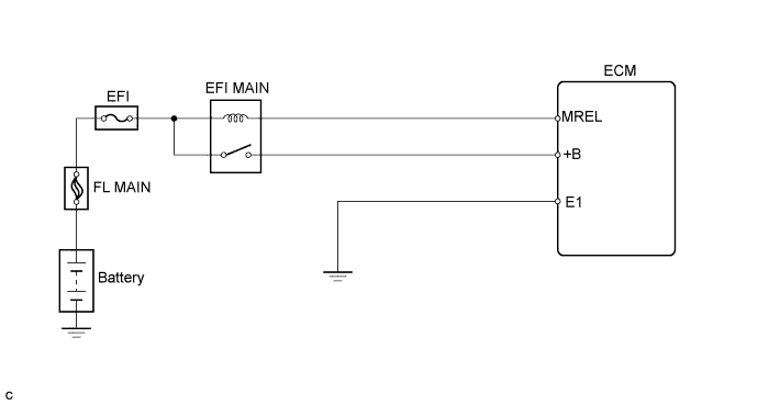
When the ignition switch is turned to ON, the battery voltage is applied to terminal IGSW of the ECM. The ECM "MREL" output signal causes a current to flow to the coil, closing the contacts of the EFI relay and supplying power to terminal +B of the ECM.
WIRING DIAGRAM
INSPECTION PROCEDURE
PROCEDURE
-
INSPECT FUSE (EFI FUSE)
-
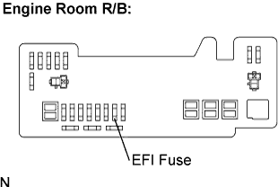
Remove the EFI fuse from the engine room R/B.
-
Measure the EFI fuse resistance.
Standard resistance Below 1 Ω -
Reinstall the EFI fuse.
NG 
CHECK FOR SHORT IN ALL HARNESS AND COMPONENTS CONNECTED TO FUSE, AND REPLACE FUSE
OK 
-
-
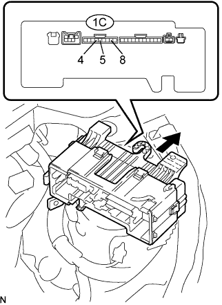
INSPECT ENGINE ROOM RELAY BLOCK (EFI RELAY)
-
Remove the engine room R/B.
-
Remove the engine room R/B lower cover.
-
Disconnect the 5 connectors from the engine room R/B.
-
Measure the EFI relay resistance.
Standard resistance Tester Connection Specified Condition 1C-4 - 1C-5 10 kΩ or higher 1C-4 - 1C-5 Below 1 Ω
(when battery voltage is applied to terminals 1C-4 and 1C-8)
-
Reinstall the engine room R/B.
NG
REPLACE ENGINE ROOM RELAY BLOCK
OK
-
-
CHECK HARNESS AND CONNECTOR (EFI RELAY - ECM, EFI RELAY - BODY GROUND)
-
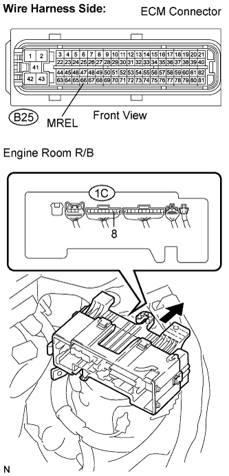
Check the harness and connectors between the ECM and the EFI relay.
-
Remove the engine room R/B.
-
Remove the engine room R/B lower cover.
-
Disconnect the B25 ECM connector.
-
Measure the resistance.
Standard resistance (Check for open) Tester Connection Specified Condition MREL (B25-66) - Engine room R/B (1C-8) Below 1 Ω Standard resistance (Check for short) Tester Connection Specified Condition MREL (B25-66) or Engine room R/B (1C-8) - Body ground 10 kΩ or higher -
Reinstall the engine room R/B.
-
Reconnect the ECM connector.
-
NG
REPAIR OR REPLACE HARNESS AND CONNECTOR
OK 
CHECK AND REPAIR HARNESS AND CONNECTOR BETWEEN EFI FUSE AND BATTERY
-