SFI SYSTEM (w/o Electronic Throttle Control System), Diagnostic DTC:P0704

| DTC Code | DTC Name |
|---|---|
| P0704 | Clutch Switch Input Circuit Malfunction |
DESCRIPTION
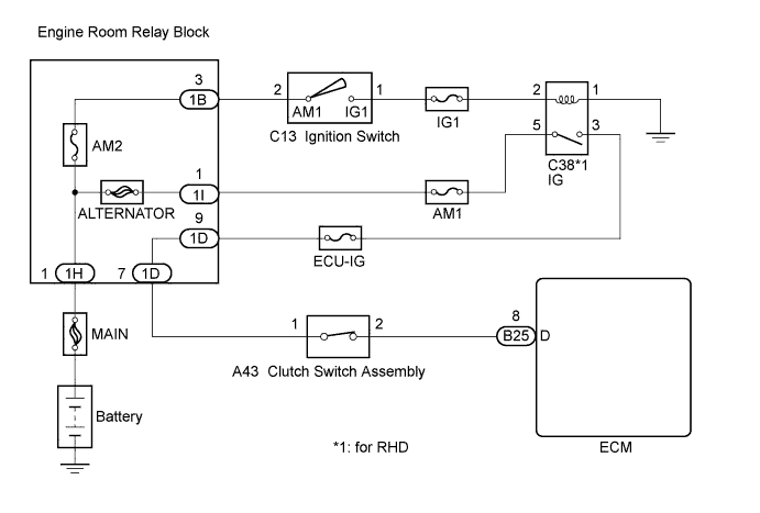
The clutch switch assembly is mounted on the clutch pedal. The switch is turned OFF when depressing the clutch pedal, and transmits a signal to the ECM.
| DTC No. | DTC Detection Condition | Trouble Area |
|---|---|---|
| P0704 | No clutch switch signals to ECM despite gears being shifted (3 trip detection logic) |
|
Tech Tips
DTC P0704 is set when the gears are shifted more than 20 times.
WIRING DIAGRAM
INSPECTION PROCEDURE
Note
Inspect the fuses for circuits related to this system before performing the following inspection procedure.
PROCEDURE
-
CHECK TERMINAL VOLTAGE
-
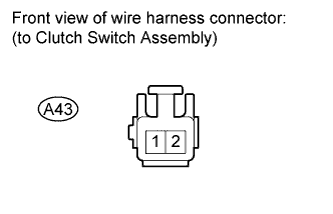
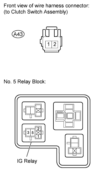
Disconnect the clutch switch assembly connector.
-
Measure the voltage according to the value(s) in the table below.
Standard Voltage Tester Connection Switch Condition Specified Condition A43-1 - Body ground Ignition switch ON 11 to 14 V -
Reconnect the clutch switch assembly connector.
NG 
CHECK HARNESS AND CONNECTOR (IG RELAY - CLUTCH SWITCH ASSEMBLY) Click here
OK 
-
-
INSPECT CLUTCH SWITCH ASSEMBLY
-
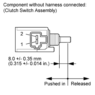
Remove the clutch switch assembly.
-
Measure the resistance according to the value(s) in the table below.
Standard Resistance Tester Connection Switch Condition Specified Condition 1 - 2 Pushed in Below 1 Ω 1 - 2 Released 10 kΩ or higher -
Reinstall the clutch switch assembly.
NG 
REPLACE CLUTCH SWITCH ASSEMBLY Click here
OK
-
-
CHECK HARNESS AND CONNECTOR (CLUTCH SWITCH ASSEMBLY - ECM)
-
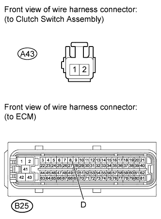
Disconnect the clutch switch assembly connector.
-
Disconnect the ECM connector.
-
Measure the resistance according to the value(s) in the table below.
Standard Resistance (Check for Open) Tester Connection Condition Specified Condition B25-8 (D) - A43-2 (Clutch switch assembly) Always Below 1 Ω Standard Resistance (Check for Short) Tester Connection Condition Specified Condition B25-8 (D) or A43-2 (Clutch switch assembly) - Body ground Always 10 kΩ or higher -
Reconnect the clutch switch assembly connector.
-
Reconnect the ECM connector.
NG
REPAIR OR REPLACE HARNESS OR CONNECTOR
OK 
REPLACE ECM Click here
-
-
CHECK HARNESS AND CONNECTOR (IG RELAY - CLUTCH SWITCH ASSEMBLY)
-
Check harness and connector (for LHD models).
-
Disconnect the clutch switch assembly connector.
-
Remove the IG relay from the No. 5 relay block.
-
Measure the resistance according to the value(s) in the table below.
Standard Resistance (Check for Open) Tester Connection Condition Specified Condition 3 (IG Relay) - A43-1 (Clutch switch assembly) Always Below 1 Ω Standard Resistance (Check for Short) Tester Connection Condition Specified Condition 3 (IG Relay) or A43-1 (Clutch switch assembly) - Body ground Always 10 kΩ or higher -
Reconnect the clutch switch assembly connector.
-
Reinstall the IG relay.
-
-
Check harness and connector (for RHD models).
-
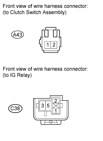
Disconnect the clutch switch assembly connector.
-
Remove the IG relay.
-
Measure the resistance according to the value(s) in the table below.
Standard Resistance (Check for Open) Tester Connection Condition Specified Condition C38-3 - A43-1
(Clutch switch assembly)
Always Below 1 Ω Standard Resistance (Check for Short) Tester Connection Condition Specified Condition C38-3 or A43-1 (Clutch switch assembly) - Body ground Always 10 kΩ or higher -
Reconnect the clutch switch assembly connector.
-
Reinstall the IG relay.
-
NG
REPAIR OR REPLACE HARNESS OR CONNECTOR
OK
-
-
INSPECT IG RELAY
-
Remove the IG relay (for RHD models).
Tech Tips
-
Remove the IG relay from the No. 5 relay block (for LHD models).
-
-
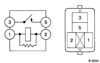
Measure the resistance according to the value(s) in the table below.
Standard Resistance Tester Connection Condition Specified Condition 3 - 5 When battery voltage absent 10 kΩ or higher 3 - 5 When battery voltage applied to terminals 1 and 2 Below 1 Ω -
Reinstall the IG relay.
NG
REPLACE IG RELAY
OK
REPAIR OR REPLACE POWER SOURCE CIRCUIT (BATTERY - IG RELAY)
-