SFI SYSTEM (w/o Electronic Throttle Control System), Diagnostic DTC:P0511

| DTC Code | DTC Name |
|---|---|
| P0511 | Idle Air Control Circuit |
DESCRIPTION
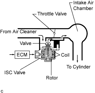
The step motor type ISC valve is located under the throttle body assembly and intake air bypassing the throttle valve is directed to the ISC valve through the passage. In this way, the intake air volume bypassing the throttle valve is regulated, controlling the engine speed. The ECM operates the ISC valve only to perform idle-up and provide feedback for the target idling speed.
| DTC No. | DTC Detection Condition | Trouble Area |
|---|---|---|
| P0511 | Open or short in ISC valve circuit (3 trip detection logic) |
|
Tech Tips
DTC P0511 is detected when the engine idles for approximately 15 seconds.
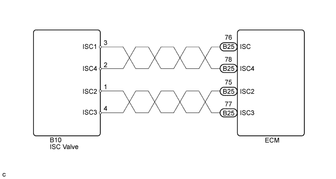
WIRING DIAGRAM
INSPECTION PROCEDURE
Tech Tips
Read freeze frame data using the intelligent tester. The ECM records vehicle and driving condition information as freeze frame data the moment a DTC is stored. When troubleshooting, freeze frame data can help determine if the vehicle was moving or stationary, if the engine was warmed up or not, if the air-fuel ratio was lean or rich, and other data from the time the malfunction occurred.
PROCEDURE
-
CHECK IDLE SPEED
-
Connect the intelligent tester to the DLC3.
-
Start the engine and turn the tester on.
-
On the intelligent tester, enter the following menus: Powertrain / Engine and ECT / Data List / Engine SPD.
-
Check the engine speed at idling.
Standard A/C OFF 790 to 890 rpm A/C ON 820 to 920 rpm -
Enter the following menus: Powertrain / Engine and ECT / Active Test / TE1.
-
Check the difference of engine speed between the ones less than 5 seconds and more then 5 seconds after switching the TE1 from OFF to ON.
Standard Difference of engine more than 100 rpm.
NG 
INSPECT ISC VALVE (RESISTANCE) Click here
OK 
CHECK FOR INTERMITTENT PROBLEMS Click here
-
-
INSPECT ISC VALVE (RESISTANCE)
-
Measure the ISC valve resistance Click here.
NG 
REPLACE THROTTLE BODY ASSEMBLY Click here
OK 
-
-
CHECK HARNESS AND CONNECTOR (ISC VALVE - ECM)
-
Disconnect the ECM connector.
-
Disconnect the ISC valve connector.
-
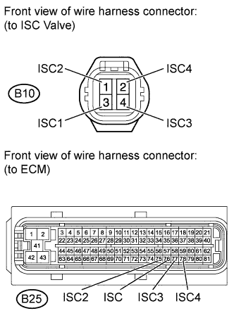
Measure the resistance according to the value(s) in the table below.
Standard Resistance (Check for Open) Tester Connection Condition Specified Condition B25-76 (ISC) - B10-3 (ISC1) Always Below 1 Ω B25-75 (ISC2) - B10-1 (ISC2) Always Below 1 Ω B25-77 (ISC3) - B10-4 (ISC3) Always Below 1 Ω B25-78 (ISC4) - B10-2 (ISC4) Always Below 1 Ω Standard Resistance (Check for Short) Tester Connection Condition Specified Condition B25-76 (ISC) or B10-3 (ISC1) - Body ground Always 10 kΩ or higher B25-75 (ISC2) or B10-1 (ISC2) - Body ground Always 10 kΩ or higher B25-77 (ISC3) or B10-4 (ISC3) - Body ground Always 10 kΩ or higher B25-78 (ISC4) or B10-2 (ISC4) - Body ground Always 10 kΩ or higher -
Reconnect the ECM connector.
-
Reconnect the ISC valve connector.
NG
REPAIR OR REPLACE HARNESS OR CONNECTOR
OK
REPLACE THROTTLE BODY ASSEMBLY Click here
-