SFI SYSTEM (w/o Electronic Throttle Control System), Diagnostic DTC:P0420

| DTC Code | DTC Name |
|---|---|
| P0420 | Catalyst System Efficiency Below Threshold (Bank 1) |
DESCRIPTION
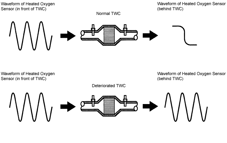
This vehicle has two heated oxygen sensors. One is located in front of the Three-Way Catalyst Converter (TWC), and the other is mounted behind the TWC. Each signal output of the sensors is converted into a waveform inside the ECM. The front heated oxygen sensor is used to monitor the air-fuel ratio by the ECM, and whose signal prompts the ECM to perform air-fuel ratio feedback control. As a result, the air-fuel ratio is balanced, and the waveform of the front heated oxygen sensor regularly oscillates between rich and lean. To determine whether or not the TWC performance has deteriorated, the ECM compares the waveforms of the front and rear heated oxygen sensors. While the TWC is functioning normally, the waveform of the rear heated oxygen sensor fluctuates between rich and lean more slowly than the front heated oxygen sensor's waveform. When the rear heated oxygen sensor's waveform frequently fluctuates, it indicates that the TWC performance deteriorates.
| DTC No. | DTC Detection Condition | Trouble Area |
|---|---|---|
| P0420 | After engine and TWC are warmed up, and while vehicle is driven within predetermined engine speed: |
|
Tech Tips
DTC P0420 is detected when the vehicle is driven at an average vehicle speed of approximately 50 km/h (31 mph) in the city for approximately 30 minutes, and then driven for approximately 15 minutes at a constant vehicle speed between 70 km/h (43 mph) and 90 km/h (56 mph) with the transmission gear selector lever in the 5th position. (If the engine speed remains 1900 to 3400 rpm and the engine load remains 25 to 50% after the catalyst is warmed up for 60 seconds or more, the detection for DTC P0420 will be performed.)
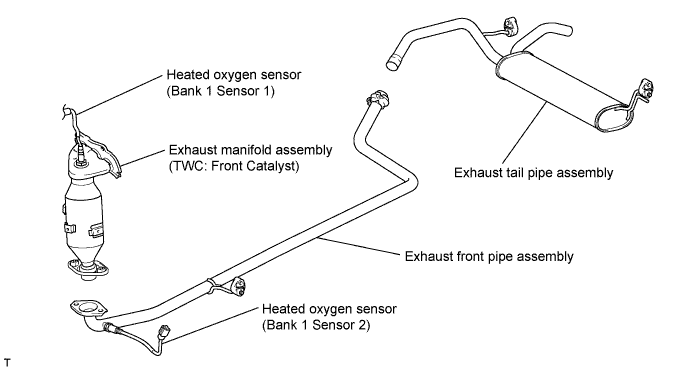
CATALYST LOCATION
INSPECTION PROCEDURE
Tech Tips
Read freeze frame data using the intelligent tester. The ECM records vehicle and driving condition information as freeze frame data the moment a DTC is stored. When troubleshooting, freeze frame data can help determine if the vehicle was moving or stationary, if the engine was warmed up or not, if the air-fuel ratio was lean or rich, and other data from the time the malfunction occurred.
PROCEDURE
-
CHECK OTHER DTC OUTPUT (IN ADDITION TO DTC P0420)
-
Connect the intelligent tester to the DLC3.
-
Turn the ignition switch to ON and turn the intelligent tester ON.
-
Select the following menu items: Powertrain / Engine and ECT / DTC.
-
Read DTCs.
Result Display (DTC Output) Proceed To P0420 A P0420 and other DTCs B Tech Tips
If any DTCs other than P0420 are output, troubleshoot those DTCs first.
B 
GO TO DTC CHART
A 
-
-
PERFORM ACTIVE TEST USING INTELLIGENT TESTER (Control the Injection Volume for A/F Sensor)
-
Perform the Active Test using the intelligent tester.
Tech Tips
The A/F Control operation lowers the injection volume by 12.5 % or increases the injection volume by 25 %.
-
Connect the intelligent tester to the DLC3.
-
Start the engine and turn the intelligent tester ON.
-
Warm up the engine.
-
Run the engine at 2,500 rpm for approximately 3 minutes.
-
On the intelligent tester, select the following menu items: Powertrain / Engine and ECT / Active Test / A/F Control.
-
Select the following monitor items: O2S B1 S1 and O2S B1 S2.
-
Perform the A/F Control operation with the engine in an idling condition (press the right or left button).
Result The heated oxygen sensor reacts in accordance with increases and decreases of the fuel injection volume: +25 % = Rich output More than 0.5 V -12.5 % = Lean output Less than 0.4 V Note
Sensor 1 (front sensor) has an output delay of a few seconds. Sensor 2 (rear sensor) has a maximum output delay of approximately 20 seconds.
Output voltage of heated oxygen sensor (sensor 1: front sensor) Output voltage of heated oxygen sensor (sensor 2: rear sensor) Mainly suspected trouble area Case 1 Injection volume
+25 %
-12.5 %

Injection volume
+25 %
-12.5 %
-
Catalyst
-
Exhaust gas leakage
Output voltage
More than 0.5 V
Less than 0.4 V

Output voltage
More than 0.5 V
Less than 0.4 V

Case 2 Injection volume
+25 %
-12.5 %
Injection volume
+25 %
-12.5 %
Sensor 1: front sensor
(sensor 1, heater, sensor 1 circuit)
Output voltage
Almost no reaction

Output voltage
More than 0.5 V
Less than 0.4 V
Case 3 Injection volume
+25 %
-12.5 %
Injection volume
+25 %
-12.5 %
Sensor 2: rear sensor
(sensor 2, heater, sensor 2 circuit)
Output voltage
More than 0.5 V
Less than 0.4 V
Output voltage
Almost no reaction
Case 4 Injection volume
+25 %
-12.5 %
Injection volume
+25 %
-12.5 %
Extremely rich or lean actual air-fuel ratio (Injector, fuel pressure, gas leakage in exhaust system, etc.) Output voltage
Almost no reaction
Output voltage
Almost no reaction
The following A/F Control procedure enables the technician to check and graph the voltage output of both the heated oxygen sensors.
To display the graph, select the following menu items on the tester: View / Line Graph.
Result Result Proceed To Case 1 A Case 2 B Case 3 C Case 4 D -
-
B
REPLACE HEATED OXYGEN SENSOR (SENSOR 1)
C 
CHECK FOR EXHAUST GAS LEAKAGE Click here
D
CHECK AND REPLACE EXTREMELY RICH OR LEAN ACTUAL AIR-FUEL RATIO, AND GO TO STEP 3
A
-
-
CHECK FOR EXHAUST GAS LEAKAGE
NG
REPAIR FOR EXHAUST GAS LEAKAGE PARTS
OK 
REPLACE EXHAUST MANIFOLD ASSEMBLY (TWC: FRONT CATALYST) Click here
-
CHECK FOR EXHAUST GAS LEAKAGE
NG
REPAIR FOR EXHAUST GAS LEAKAGE PARTS
OK
REPLACE HEATED OXYGEN SENSOR (SENSOR 2)