SFI SYSTEM (w/o Electronic Throttle Control System), Diagnostic DTC:P0341, P0342, P0343

| DTC Code | DTC Name |
|---|---|
| P0341 | Camshaft Position Sensor "A" Circuit Range / Performance (Bank 1 or Single Sensor) |
| P0342 | Camshaft Position Sensor Circuit Low Input |
| P0343 | Camshaft Position Sensor Circuit High Input |
DESCRIPTION
The camshaft position sensor consists of a magnet and an iron core which is wrapped with copper wire, and is installed on the cylinder head. When the camshaft rotates, each of 3 teeth on the camshaft passes through the camshaft position sensor. This activates the internal magnet in the sensor, generating a voltage in the copper wire. The camshaft rotation is synchronized with the crankshaft rotation. When the crankshaft turns twice the voltage is generated 3 times in the camshaft position sensor. The generated voltage in the sensor acts as a signal, allowing the ECM to locate the camshaft position. This signal is then used to control ignition timing, fuel injection timing, and the VVT system.
| DTC No. | DTC Detection Condition | Trouble Area |
|---|---|---|
| P0341 | Abnormal pulse of camshaft position sensor occurs 12 times or more totally in 1 driving cycle (3 trip detection logic) |
|
| P0342 | Camshaft position sensor output stays low (3 trip detection logic) |
|
| P0343 | Camshaft position sensor output stays high (3 trip detection logic) |
|
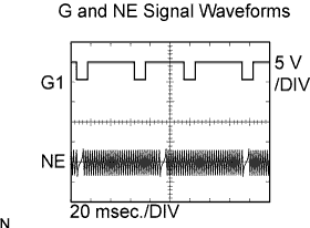
The correct waveform is as shown below.
G1 stands for the camshaft position sensor signal, and NE+ stands for the crankshaft position sensor signal.
| Item | Contents |
|---|---|
| Terminal | CH1: G1 - E1 CH2: NE+ - NE- |
| Equipment Setting | 5 V/Division, 20 ms/Division |
| Condition | While cranking or idling |
Tech Tips
These DTCs are detected when the engine is running or the engine cranks 12 revolutions or more.
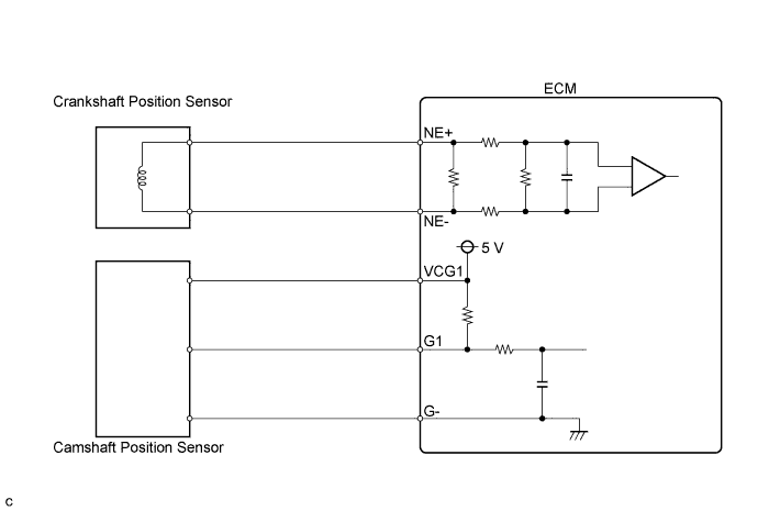
WIRING DIAGRAM
INSPECTION PROCEDURE
Tech Tips
Read freeze frame data using the intelligent tester. The ECM records vehicle and driving condition information as freeze frame data the moment a DTC is stored. When troubleshooting, freeze frame data can help determine if the vehicle was moving or stationary, if the engine was warmed up or not, if the air-fuel ratio was lean or rich, and other data from the time the malfunction occurred.
PROCEDURE
-
CHECK HARNESS AND CONNECTOR (CAMSHAFT POSITION SENSOR - ECM)
-
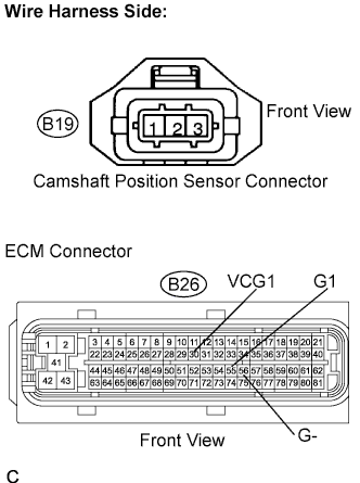
Disconnect the B19 camshaft position sensor connector.
-
Disconnect the B26 ECM connector.
-
Measure the resistance.
Standard resistance (Check for open) Tester Connection Specified Condition Camshaft position sensor (B19-1) - G1 (B26-55) Below 1 Ω Camshaft position sensor (B19-2) - G- (B26-56) Below 1 Ω Camshaft position sensor (B19-3) - VCG1 (B26-30) Below 1 Ω Standard resistance (Check for short) Tester Connection Specified Condition Camshaft position sensor (B19-1) or G1 (B26-55) - Body ground 10 kΩ or higher Camshaft position sensor (B19-3) or VCG1 (B26-30) - Body ground 10 kΩ or higher -
Reconnect the camshaft position sensor connector.
-
Reconnect the ECM connectors.
NG 
REPAIR OR REPLACE HARNESS AND CONNECTOR
OK 
-
-
INSPECT CAM POSITION SENSOR (SENSOR INSTALLATION)
-
Check the sensor installation.
OK The sensor is installed correctly.
NG
REPAIR OR REPLACE CAM POSITION SENSOR
OK
-
-
INSPECT CAMSHAFT
-
Check the teeth of the camshaft.
OK The teeth do not have any cracks or deformation.
NG
REPLACE CAMSHAFT
OK
-
-
REPLACE CAM POSITION SENSOR
NEXT
-
CHECK IF DTC OUTPUT RECURS
-
Start the engine.
-
Stop the engine and wait for at least 10 seconds.
-
Connect the intelligent tester to the DLC3.
-
Select the following menu items: Powertrain / Engine and ECT / DTC / Pending.
Result Display (DTC Output) Proceed To No output A P0341, P0342 or P0343 B
B
REPLACE ECM
A 
END
-