SFI SYSTEM (w/o Electronic Throttle Control System), Diagnostic DTC:P0122, P0123

| DTC Code | DTC Name |
|---|---|
| P0122 | Throttle Position Sensor Circuit Low Input |
| P0123 | Throttle Position Sensor Circuit High Input |
DESCRIPTION
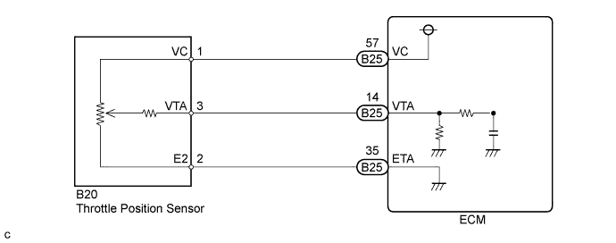
The throttle position sensor is mounted on the throttle body assembly and detects the throttle valve opening angle. When the throttle valve is fully closed, a voltage of approximately 0.4 to 0.9 V is applied to terminal VTA of the ECM. The voltage applied to terminal VTA of the ECM increases in proportion to the opening angle of the throttle valve and becomes approximately 3.6 to 4.3 V when the throttle valve is fully open. The ECM monitors the vehicle driving conditions through these signals input from terminal VTA, and uses them as one of the conditions for determining the air-fuel ratio correction, power increase correction and fuel-cut control, etc.
Tech Tips
When the throttle position sensor output voltage is outside the normal range, the ECM determines this as a malfunction.
| DTC No. | DTC Detection Condition | Trouble Area |
|---|---|---|
| P0122 | VTA stays less than 3.14% for 0.08 seconds or more (3 trip detection logic) |
|
| P0123 | VTA stays more than 95.7% for 0.08 seconds or more (3 trip detection logic) |
|
Tech Tips
-
These DTCs are detected when the engine idles for approximately 15 seconds.
-
After confirming DTCs, confirm the throttle valve opening percentage and closed throttle position switch condition using the intelligent tester.
| Throttle Valve Fully Closed | Throttle Valve Fully Open | Trouble Area |
|---|---|---|
| 7 to 18% | Approximately 75 to 95% | - (Normal) |
| 0% | 0% |
|
| Approximately 100% | Approximately 100% |
|
FAIL-SAFE
If DTC P0122 or P0123 is detected, the ECM performs engine control using a throttle position calculated from the engine speed.
WIRING DIAGRAM
INSPECTION PROCEDURE
Tech Tips
Read freeze frame data using the intelligent tester. The ECM records vehicle and driving condition information as freeze frame data the moment a DTC is stored. When troubleshooting, freeze frame data can help determine if the vehicle was moving or stationary, if the engine was warmed up or not, if the air-fuel ratio was lean or rich, and other data from the time the malfunction occurred.
PROCEDURE
-
READ VALUE USING INTELLIGENT TESTER (Throttle POS)
-
Connect the intelligent tester to the DLC3.
-
Turn the ignition switch to ON (do not start the engine).
-
Enter the following menus: Powertrain / Engine and ECT / Data List / Throttle POS.
-
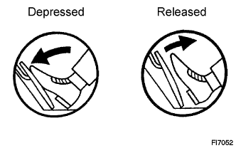
Read the value displayed on the tester when the accelerator pedal is operated (releasing and depressing).
Result Result Proceed to 0 A Approximately 8 to 88 (Varies according to accelerator pedal opening position) B Approximately 100 C
B 
CHECK FOR INTERMITTENT PROBLEMS Click here
C 
INSPECT THROTTLE POSITION SENSOR (SENSOR RESISTANCE) Click here
A 
-
-
INSPECT THROTTLE POSITION SENSOR (SENSOR RESISTANCE)
-
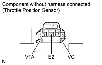
Disconnect the throttle position sensor connector.
-
Measure the resistance according to the value(s) in the table below.
Standard Resistance Tester Connection Condition Specified Condition 1 (VC) - 2 (E2) Always 2.5 to 5.0 kΩ 3 (VTA) - 2 (E2) Always 0.3 to 6.0 kΩ -
Reconnect the throttle position sensor connector.
NG
REPLACE THROTTLE BODY ASSEMBLY Click here
OK
-
-
CHECK HARNESS AND CONNECTOR (THROTTLE POSITION SENSOR - ECM)
-
Disconnect the ECM connector.
-
Disconnect the throttle position sensor connector.
-
Measure the resistance according to the value(s) in the table below.
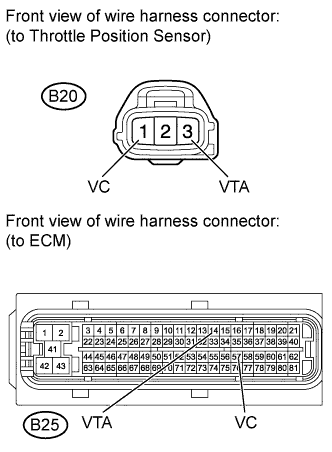
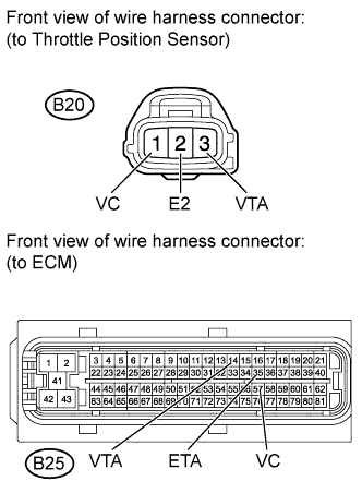
Standard Resistance (Check for Short) Tester Connection Condition Specified Condition B20-1 (VC) or B25-57 (VC) - Body ground Always 10 kΩ or higher B20-3 (VTA) or B25-14 (VTA) - Body ground Always 10 kΩ or higher -
Reconnect the throttle position sensor connector.
-
Reconnect the ECM connector.
NG
REPAIR OR REPLACE HARNESS OR CONNECTOR
OK 
REPLACE ECM Click here
-
-
INSPECT THROTTLE POSITION SENSOR (SENSOR RESISTANCE)
-
Disconnect the throttle position sensor connector.
-
Measure the resistance according to the value(s) in the table below.
Standard Resistance Tester Connection Condition Specified Condition 1 (VC) - 2 (E2) Always 2.5 to 5.0 kΩ 3 (VTA) - 2 (E2) Always 0.3 to 6.0 kΩ -
Reconnect the throttle position sensor connector.
NG
REPLACE THROTTLE BODY ASSEMBLY Click here
OK
-
-
CHECK HARNESS AND CONNECTOR (THROTTLE POSITION SENSOR - ECM)
-
Disconnect the ECM connector.
-
Disconnect the throttle position sensor connector.
-
Measure the resistance according to the value(s) in the table below.
Standard Resistance (Check for Open) Tester Connection Condition Specified Condition B20-1 (VC) - B25-57 (VC) Always Below 1 Ω B20-3 (VTA) - B25-14 (VTA) Always Below 1 Ω B20-2 (E2) - B25-35 (ETA) Always Below 1 Ω Standard Resistance (Check for +B Short) Tester Connection Condition Specified Condition B20-1 (VC) or B25-57 (VC) - B20-3 (VTA) or B25-14 (VTA) Always 10 kΩ or higher -
Reconnect the throttle position sensor connector.
-
Reconnect the ECM connector.
NG
REPAIR OR REPLACE HARNESS OR CONNECTOR
OK
REPLACE ECM Click here
-