SFI SYSTEM (w/o Electronic Throttle Control System) DIAGNOSIS SYSTEM

-
DESCRIPTION
-

When troubleshooting Euro-OBD vehicles, the only difference from the usual troubleshooting procedure is that you connect an OBD scan tool (complying with ISO 15031-4) or an intelligent tester to the vehicle, and read the various data output from the vehicle's ECM.
-
Euro-OBD regulations require that the vehicle's on-board computer illuminates the MIL (Malfunction Indicator Lamp) on the instrument panel when the computer detects a malfunction in: 1) the emission control systems and components, 2) the powertrain control components (which affect vehicle emissions), or 3) the computer. In addition, the applicable DTCs (Diagnostic Trouble Codes) prescribed by ISO 15031-4 are recorded in the ECM memory.
If the malfunction does not recur in 3 consecutive trips, the MIL goes off automatically but the DTCs remain recorded in the ECM memory.
-
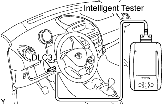
To check the DTCs, connect the OBD scan tool or intelligent tester to the DLC3 (Data Link Connector 3) on the vehicle. The OBD scan tool or intelligent tester also enables you to erase the DTCs and check the freeze frame data and various forms of engine data. (See the instruction manual for the OBD scan tool or intelligent tester.)
-
*2 trip detection logic: When a malfunction is first detected, the malfunction is temporarily stored in the ECM memory (1st trip). If the ignition switch is turned OFF and then to ON again, and the same malfunction is detected again, the MIL illuminates (2nd trip).
-
Freeze frame data: The ECM records vehicle and driving condition information as freeze frame data the moment a DTC is stored. When troubleshooting, freeze frame data can be helpful in determining whether the vehicle was running or stopped, whether the engine was warmed up or not, whether the air/fuel ratio was lean or rich, as well as other data recorded at the time of a malfunction.
-
-
CHECK DLC3
-
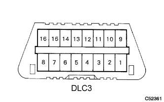
The vehicle's ECM uses the ISO 9141-2 (Euro-OBD) communication protocol. The terminal arrangement of the DLC3 complies with ISO 15031-03 and matches the ISO 9141-2 format.
Symbol Terminal No. Name Reference Terminal Result Condition SIL 7 Bus"+" line 5 - Signal ground Pulse generation During transmission CG 4 Chassis ground Body ground 1 Ω or less Always SG 5 Signal ground Body ground 1 Ω or less Always BAT 16 Battery positive Body ground 9 to 14 V Always Tech Tips
When you use the intelligent tester, first connect the cable of the tester to the DLC3. Next, turn the ignition switch to ON. Finally turn the tester ON. If the screen displays a communication error massage and bus check also fails, a problem exists in the vehicle, the tester or the tester cable.
-
If communication is normal when the tester is connected to another vehicle, inspect the DLC3 on the original vehicle.
-
If communication is still not possible when the tester is connected to another vehicle, the problem is probably in the tester or the cable, so consult the Service Department listed in its instruction manual.
-
-
-
INSPECT BATTERY VOLTAGE
-
Inspect the battery voltage.
If the voltage is below 11 V, recharge the battery before proceeding.
-
-
CHECK MIL
-
The MIL illuminates when the ignition switch is turned to ON and the engine is not running.
Tech Tips
If the MIL does not illuminate, check the MIL circuit.
-
The MIL should go off when the engine is started. If the MIL remains on, the diagnosis system has detected a malfunction or abnormality in the system.
-