SFI SYSTEM (w/ Electronic Throttle Control System) MIL Circuit
DESCRIPTION
The MIL (Malfunction Indicator Lamp) is used to indicate vehicle malfunction detections by the ECM. By turning the ignition switch to ON, the power is supplied to the MIL circuit, and the ECM provides the circuit ground that illuminates the MIL.
Operation of the MIL should be checked visually:
When the ignition switch is first turned to ON, the MIL should be illuminated. If it remains OFF or ON, use the intelligent tester and follow the procedure below to determine cause of the problem.
WIRING DIAGRAM

INSPECTION PROCEDURE
Note
After replacing the ECM, perform electronic throttle learning Click here.
Inspect the fuses for circuits related to this system before performing the following inspection procedure.
PROCEDURE
-
CHECK MIL CONDITION
-
Perform troubleshooting in accordance with the table below.
Result Result Proceed to MIL remains ON A MIL is not illuminated B
B 
CHECK MIL CONDITION Click here
A 
-
-
CHECK WHETHER MIL GOES OFF
-
Connect the intelligent tester to the DLC3.
-
Turn the ignition switch to ON and turn the tester on.
-
Enter the following menus: Powertrain / Engine and ECT/ DTC.
-
Check if DTCs have been stored. Note down if there are DTCs.
-
Enter the following menus: Powertrain / Engine and ECT / DTC / Clear.
-
Clear DTC.
-
Check if the MIL goes off.
OK The MIL should go off.
NG
CHECK HARNESS AND CONNECTOR (CHECK FOR SHORT IN WIRE HARNESS) Click here
OK 
CHECK FOR INTERMITTENT PROBLEMS Click here
-
-
CHECK HARNESS AND CONNECTOR (CHECK FOR SHORT IN WIRE HARNESS)
-
Disconnect the ECM connector.
-
Check if the MIL goes off.
OK The MIL should go off. -
Reconnect the ECM connector.
-
Reconnect the combination meter connector.
NG
CHECK HARNESS AND CONNECTOR (COMBINATION METER - ECM) Click here
OK
REPLACE ECM Click here
-
-
CHECK HARNESS AND CONNECTOR (COMBINATION METER - ECM)
-
Disconnect the combination meter connector.
-
Disconnect the ECM connector.
-
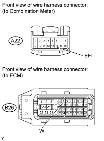
Measure the resistance according to the value(s) in the table below.
Standard Resistance (Check for Short) Tester Connection Condition Specified Condition B26-5 (W) or A22-14 (EFI) - Body ground Always 10 kΩ or higher -
Reconnect the combination meter connector.
-
Reconnect the ECM connector.
NG 
REPAIR OR REPLACE HARNESS OR CONNECTOR
OK
REPAIR OR REPLACE COMBINATION METER ASSEMBLY
-
-
CHECK MIL CONDITION
-
Check if the MIL illuminates when turning the ignition switch to ON.
OK The MIL should be illuminated.
NG
CHECK COMBINATION METER ASSEMBLY (MIL CIRCUIT) Click here
OK
END
-
-
CHECK COMBINATION METER ASSEMBLY (MIL CIRCUIT)
-
Check the MIL circuit Click here.
NG
REPAIR OR REPLACE HARNESS OR CONNECTOR
OK
CHECK FOR INTERMITTENT PROBLEMS Click here
-