SFI SYSTEM (w/ Electronic Throttle Control System) Starter Signal Circuit
DESCRIPTION
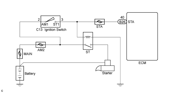
When the engine is cranked, the intake air flow is slow, so fuel vaporization is poor. A rich mixture is therefore necessary in order to achieve good startability. While the engine is being cranked, the battery voltage is applied to terminal STA of the ECM. The starter signal is mainly used to increase the fuel injection volume for the starting injection control and after-start injection control.
WIRING DIAGRAM
INSPECTION PROCEDURE
Note
After replacing the ECM, perform electronic throttle learning Click here.
PROCEDURE
-
INSPECT STARTER SIGNAL
-
Connect the intelligent tester to the DLC3.
-
Turn the ignition switch to ON and turn the tester on.
-
Enter the following menus: Powertrain / Engine and ECT / Data List / Starter SIG.
-
Check the result when the ignition switch is turned to ON and START.
OK Ignition Switch Position ON START STARTER SIG OFF ON
NG 
CHECK HARNESS AND CONNECTOR (ECM - IGNITION SWITCH) Click here
OK 
PROCEED TO NEXT SUSPECTED AREA SHOWN IN PROBLEM SYMPTOMS TABLE Click here
-
-
CHECK HARNESS AND CONNECTOR (ECM - IGNITION SWITCH)
-
Disconnect the ECM connector.
-
Disconnect the ignition switch connector.
-
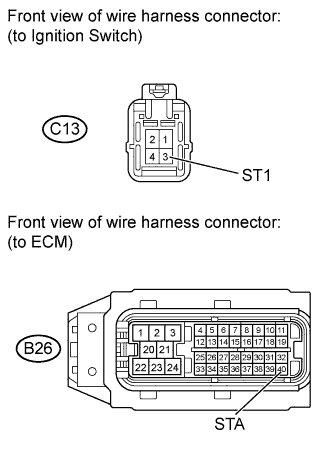
Measure the resistance according to the value(s) in the table below.
Standard Resistance (Check for Open) Tester Connection Condition Specified Condition B26-40 (STA) - C13-3 (ST1) Always Below 1 Ω Standard Resistance (Check for Short) Tester Connection Condition Specified Condition E26-40 (STA) or C13-3 (ST1) - Body ground Always 10 kΩ or higher -
Reconnect the ECM connector.
-
Reconnect the ignition switch connector.
NG 
REPAIR OR REPLACE HARNESS OR CONNECTOR
OK
REPLACE ECM Click here
-