SFI SYSTEM (w/ Electronic Throttle Control System), Diagnostic DTC:U0101

| DTC Code | DTC Name |
|---|---|
| U0101 | Lost Communication with TCM |
DESCRIPTION
The ECM intercommunicates with the transmission control ECU through the Controller Area Network (CAN).
If there is a problem in this intercommunication, the ECM illuminates the MIL and sets a DTC.
| DTC No. | DTC Detection Condition | Trouble Area |
|---|---|---|
| U0101 |
|
|
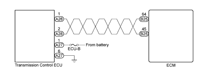
WIRING DIAGRAM
INSPECTION PROCEDURE
Tech Tips
If the CAN communication malfunctions, the transmission control ECU cannot receive the current data from the ECM. In this case, the freeze frame data output from the transmission control ECU has not been updated so it will not be useful information for the inspection procedure. However, reading the Data List as the first step of troubleshooting is effective for finding malfunctions.
Note
After replace the ECM, perform electronic throttle learning Click here
PROCEDURE
-
CHECK OTHER DTC OUTPUT (IN ADDITION TO DTC U0101)
-
Connect the intelligent tester to the DLC3.
-
Turn the ignition switch to ON and turn the tester ON.
-
Select the following menu items: Powertrain / Engine and ECT / DTC.
-
Read DTCs.
Result Display (DTC Output) Proceed to U0101 A U0101 and other DTCs B Tech Tips
If any DTCs other than U0101 are output, troubleshoot those DTCs first.
B 
GO TO DTC CHART
A 
-
-
INSPECT TRANSMISSION CONTROL ECU
-
Disconnect the Transmission Control ECU (TCM) connector.
-
Turn the ignition switch to ON.
-
Measure the voltage.
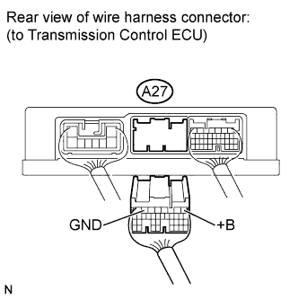
Standard voltage Tester Connection Specified Condition +B (A27-1) - Body ground 9 to 14 V -
Measure the resistance.
Standard resistance Tester Connection Specified Condition GND (A27-6) - Body ground Below 1 Ω -
Reconnect the transmission control ECU connector.
NG
REPAIR OR REPLACE HARNESS AND CONNECTOR (BATTERY - TCM, TCM - BODY GROUND)
OK
-
-
CHECK HARNESS AND CONNECTOR (TRANSMISSION CONTROL ECU - ECM)
-
Disconnect the ECM connector.
-
Disconnect the transmission control ECU connector.
-
Measure the resistance.
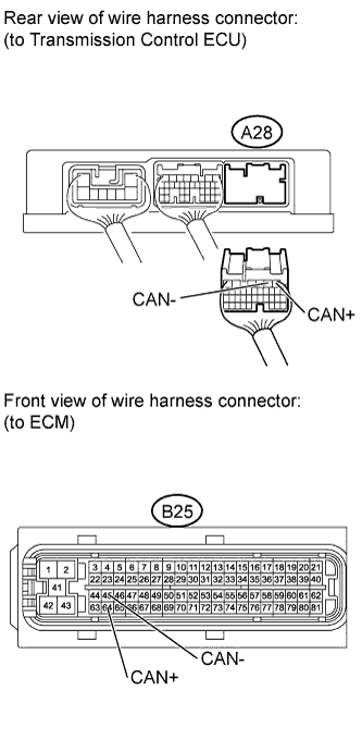
Standard resistance (Check for open) Tester Connection Specified Condition CAN+ (B25-64) - CAN+ (A28-1) Below 1 Ω CAN- (B25-45) - CAN- (A28-2) Below 1 Ω Standard resistance (Check for short) Tester Connection Specified Condition CAN+ (B25-64) or CAN+ (A28-1) - Body ground 10 kΩ or higher CAN- (B25-45) or CAN- (A28-2) - Body ground 10 kΩ or higher -
Reconnect the transmission control ECU connector.
-
Reconnect the ECM connector.
NG
REPAIR OR REPLACE HARNESS AND CONNECTOR
OK
-
-
REPLACE ECM
-
Replace ECM Click here.
Note
After replace the ECM, perform electronic throttle learning Click here.
NEXT
-
-
CHECK WHETHER DTC OUTPUT RECURS (DTC U0101)
-
Connect the intelligent tester to the DLT3.
-
Turn the ignition switch to ON and turn the tester ON.
-
Select the following menu items: Powertrain / Engine and ECT / DTC.
-
Read DTCs.
Result Display (DTC Output) Proceed to No output A U0101 B
B
REPLACE TRANSMISSION CONTROL ECU
A 
END
-