SFI SYSTEM (w/ Electronic Throttle Control System), Diagnostic DTC:P0562, P0563

| DTC Code | DTC Name |
|---|---|
| P0562 | System Voltage Low |
| P0563 | System Voltage High |
DESCRIPTION
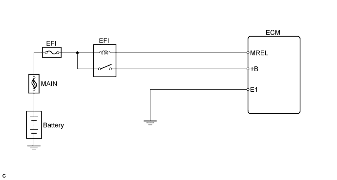
When the ignition switch is turned to ON, the battery voltage is applied to terminal +B of the ECM.
| DTC No. | DTC Detection Condition | Trouble Area |
|---|---|---|
| P0562 | Battery voltage is between 2.5 V and 10 V when 180 seconds or more have elapsed since engine start (3 trip detection logic) |
|
| P0563 | Battery voltage is 17 V or more when vehicle speed is 25 km/h (16 mph) or more, after 180 seconds or more have elapsed since engine start (3 trip detection logic). |
|
Tech Tips
-
DTC P0562 is detected when the engine idles for 180 seconds or more.
-
DTC P0563 is detected when the vehicle speed is 25 km/h (16 mph) or more and 180 seconds or more have elapsed since engine start.
WIRING DIAGRAM
INSPECTION PROCEDURE
Note
After replace the ECM, perform electronic throttle learning Click here.
Tech Tips
Read freeze frame data using the intelligent tester. The ECM records vehicle and driving condition information as freeze frame data the moment a DTC is stored. When troubleshooting, freeze frame data can help determine if the vehicle was moving or stationary, if the engine was warmed up or not, if the air-fuel ratio was lean or rich, and other data from the time the malfunction occurred.
PROCEDURE
-
CHECK OUTPUT DTCS
-
Connect the intelligent tester to the DLC3.
-
Turn the ignition switch to ON and turn the intelligent tester ON.
-
Select the following menu items: Powertrain / Engine and ECT / DTC.
-
Read DTCs.
Result Display (DTC Output) Proceed To P0562 A P0563 B
B 
INSPECT CHARGING SYSTEM AND BATTERY Click here
A 
-
-
INSPECT FUSE (EFI FUSE)
-
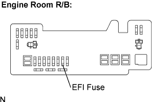
Remove the EFI fuse from the engine room R/B.
-
Measure the EFI fuse resistance.
Standard resistance Below 1 Ω -
Reinstall the EFI fuse.
NG 
CHECK FOR SHORT IN ALL HARNESSES AND COMPONENTS CONNECTED TO FUSE
OK
-
-
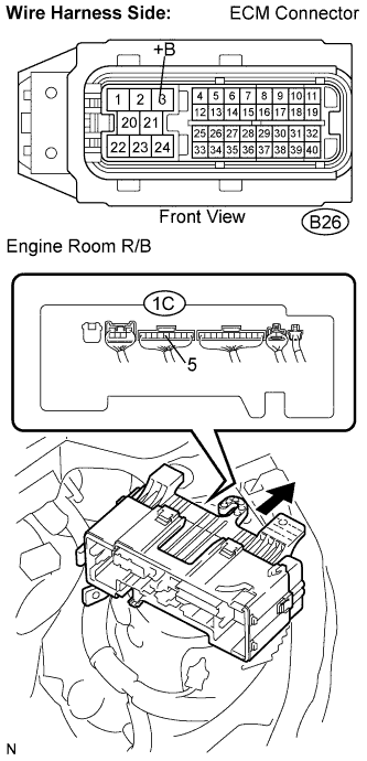
CHECK HARNESS AND CONNECTOR (ENGINE ROOM R/B - ECM)
-
Remove the engine room R/B.
-
Remove the engine room R/B lower cover.
-
Disconnect the B26 ECM connector.
-
Measure the resistance.
Standard resistance (Check for open) Tester Connection Specified Condition +B (B26-3) - Engine room R/B (1C-5) Below 1 Ω Engine room R/B (1C-5) - Battery cable Below 1 Ω Standard resistance (Check for short) Tester Connection Specified Condition +B (B26-3) or Engine room R/B (1C-5) and (5) - Body ground 10 kΩ or higher -
Reinstall the engine room R/B.
-
Reconnect the ECM connector.
NG
REPAIR OR REPLACE HARNESS AND CONNECTOR
OK
-
-
INSPECT CHARGING SYSTEM AND BATTERY
NG
REPAIR OR REPLACE CHARGING SYSTEM AND BATTERY
OK 
REPLACE ECM