SFI SYSTEM (w/ Electronic Throttle Control System), Diagnostic DTC:P0501

| DTC Code | DTC Name |
|---|---|
| P0501 | Vehicle Speed Sensor Range / Performance |
DESCRIPTION
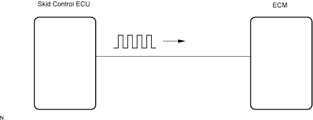
Vehicles detect the vehicle speed using the skid control ECU and wheel speed sensor. The wheel speed sensor monitors the wheel rotation speed and sends a signal to the skid control ECU. The skid control ECU converts the wheel speed signal into a 4-pulse signal and transmits it to the ECM. The ECM determines the vehicle speed based on the frequency of the pulse signal.
| DTC No. | DTC Detection Condition | Trouble Area |
|---|---|---|
| P0501 | While vehicle is driven, no vehicle speed sensor signal to ECM (3 trip detection logic) |
|
Tech Tips
-
DTC P0501 is detected when the vehicle continues to decelerate for more than 3 seconds after driving at the engine speed of 3,000 rpm or more (any gear position).
-
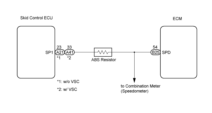
The vehicles equipped with the ABS resistor have a resistor on the wire between the ECM and the skid control ECU (see WIRING DIAGRAM).
WIRING DIAGRAM
INSPECTION PROCEDURE
Note
After replace the ECM, perform electronic throttle learning Click here.
Tech Tips
Read freeze frame data using the intelligent tester. The ECM records vehicle and driving condition information as freeze frame data the moment a DTC is stored. When troubleshooting, freeze frame data can help determine if the vehicle was moving or stationary, if the engine was warmed up or not, if the air-fuel ratio was lean or rich, and other data from the time the malfunction occurred.
PROCEDURE
-
CHECK VEHICLE SPEED VALUE
-
Connect the intelligent tester to the DLC3.
-
Start the engine and turn the intelligent tester ON.
-
On the intelligent tester, select the following menu items: Powertrain / Engine and ECT / Data List / Vehicle SPD.
-
Check the vehicle speed when the vehicle is running.
OK Same value as the actual vehicle speed.
OK 
CHECK FOR INTERMITTENT PROBLEMS
NG 
-
-
CHECK HARNESS AND CONNECTOR (SKID CONTROL ECU - ECM)
-
Disconnect the B25 ECM connector.
-
Disconnect the A21 or the A41 skid control ECU connector.
-
Measure the resistance.
Tech Tips
When checking for an open circuit, the wire resistance between connectors indicates a value including the resistance of the ABS resistor.
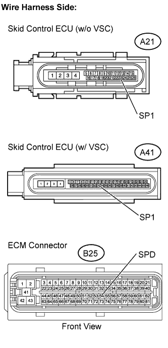
Standard resistance (Check for open) Tester Connection Specified Condition w/o VSC
SPD (B25-54) - SP1 (A21-23)
19 to 22 Ω w/ VSC
SPD (B25-54) - SP1 (A41-33)
19 to 22 Ω Standard resistance (Check for short) Tester Connection Specified Condition w/o VSC
SPD (B25-54) or SP1 (A21-23) - Body ground
10 kΩ or higher w/ VSC
SPD (B25-54) or SP1 (A41-33) - Body ground
10 kΩ or higher -
Reconnect the ECM connector.
-
Reconnect the skid control ECU connector.
NG
REPAIR OR REPLACE HARNESS AND CONNECTOR
OK
-
-
CHECK COMBINATION METER ASSEMBLY (SPEEDOMETER OPERATION)
-
Drive the vehicle and check if the operation of the speedometer in the combination meter is normal.
OK Operation of the speedometer in the combination meter is normal. Tech Tips
-
The vehicle speed sensor is operating normally if the speedometer reading is normal.
-
If the speedometer reading is abnormal, refer to the speedometer circuit inspection procedure Click here.
-
NG
CHECK SPEEDOMETER CIRCUIT
OK 
REPLACE ECM
-