SFI SYSTEM (w/ Electronic Throttle Control System), Diagnostic DTC:P0300, P0301, P0302, P0303

| DTC Code | DTC Name |
|---|---|
| P0300 | Random / Multiple Cylinder Misfire Detected |
| P0301 | Cylinder 1 Misfire Detected |
| P0302 | Cylinder 2 Misfire Detected |
| P0303 | Cylinder 3 Misfire Detected |
DESCRIPTION
When a misfire occurs in the engine, hydrocarbons (HC) enter the exhaust gas in high concentrations. If this HC concentration is high enough, there could be an increase in exhaust emission levels. High concentrations of HC can also cause the temperature of the Three-Way Catalytic Converter (TWC) to increase, possibly damaging the TWC. To prevent this increase in emissions and limit the possibility of thermal damage, the ECM monitors the misfire rate. When the temperature of the TWC reaches a point of thermal degradation, the ECM blinks the MIL. For monitoring misfire, the ECM uses both the camshaft position sensor and the crankshaft position sensor. The camshaft position sensor is used to identify misfiring cylinders and the crankshaft position sensor is used to measure variations in the crankshaft rotation speed. The misfire counters increments when crankshaft rotation speed variations exceed the threshold values.
If the misfiring rate exceeds the threshold and could cause emission deterioration, the ECM illuminates the MIL.
Tech Tips
-
When a misfire occurs, which results in damage to the TWC, the MIL blinks during every 200 engine revolutions.
-
For any particular 1,000 revolutions of the engine, misfiring which could result in emission deterioration is detected. This causes the MIL to illuminate.
| DTC No. | DTC Detection Condition | Trouble Area |
|---|---|---|
| P0300 | Misfiring of random cylinders is detected (2 trip detection logic) |
|
| P0301 P0302 P0303 |
Misfiring of each cylinder is detected (2 trip trip detection detection logic) |
|
Tech Tips
These DTCs are detected when the engine idles for approximately 10 minutes after warm-up. (Misfire can be clearly checked by activating the air conditioning system.)
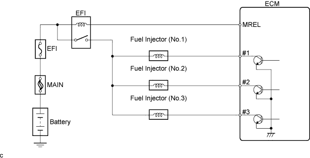
WIRING DIAGRAM
CONFIRMATION DRIVING PATTERN
Allow the engine to idle for 10 minutes or more.
INSPECTION PROCEDURE
Tech Tips
-
If any DTCs other than the misfire DTCs are set simultaneously, first troubleshoot them.
-
If a misfire does not occur when the vehicle is brought to the workshop, a misfire can be confirmed by reproducing the condition of the freeze frame data. Also, after finishing repairs, confirm that misfires do not recur (see the confirmation driving pattern).
-
Read freeze frame data using the intelligent tester. The ECM records vehicle and driving condition information as freeze frame data the moment a DTC is stored. When troubleshooting, freeze frame data can help determine if the vehicle was moving or stationary, if the engine was warmed up or not, if the air-fuel ratio was lean or rich, and other data from the time the malfunction occurred.
-
When either of Short FT #1 and Long FT #1 in the freeze frame data is over the range of -20 %, there is a possibility that the air-fuel ratio is becoming rich (-20 % or less) or lean (+20 % or more).
-
When Coolant Temp. in the freeze frame data is less than 75°C (167°F), there is a possibility that misfires occur only during engine warm-up.
-
If a misfire cannot be reproduced, the following reasons may apply: 1) the vehicle has a lack of fuel, 2) improper fuel is being used, and 3) the ignition plug has been contaminated.
PROCEDURE
-
CHECK OTHER DTC OUTPUT (IN ADDITION TO P0300, P0301, P0302 OR P0303)
-
Connect the intelligent tester to the DLC3.
-
Turn the ignition switch to ON and turn the intelligent tester ON.
-
Select the following menu items: Powertrain / Engine and ECT / DTC.
-
Read DTCs.
Result Display (DTC Output) Proceed To P0300, P0301, P0302 and/or P0303 A P0300, P0301, P0302 and/or P0303 and other DTCs. B Tech Tips
If any DTCs other than P0300, P0301, P0302 and P0303 are output, troubleshoot those DTCs first.
B 
GO TO DTC CHART
A 
-
-
CHECK HARNESS AND CONNECTOR (CONNECTION CONDITION OF ENGINE WIRE HARNESS)
-
Check the connection of the wire harnesses and connector.
OK Connected correctly and no damage on the wire harnesses.
NG
REPAIR OR REPLACE HARNESS AND CONNECTOR
OK
-
-
CHECK OUTPUT DTCS
-
Connect the intelligent tester to the DLC3.
-
Turn the ignition switch to ON and turn the intelligent tester ON.
-
Start the engine.
-
On the intelligent tester, select the following menu items: Powertrain / Engine and ECT / DTC.
Tech Tips
Read the output DTCs and proceed to the appropriate step shown in the table below.
Result Number of Misfire Cylinder DTC Proceed To 1 DTC (other than DTC P0300) A 2 DTCs or more (other than DTC P0300) B
B 
CHECK VALVE TIMING Click here
A
-
-
CHECK SPARK PLUG
-
Remove the ignition coil assembly.
-
Remove the spark plug.
-
Check the spark plug type.
Supplier Type DENSO K20HR - U11 -
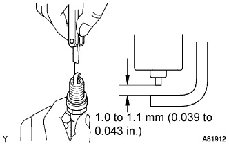
Check the spark plug electrode gap.
Standard 1.0 to 1.1 mm (0.039 to 0.043 in.) Maximum 1.2 mm (0.047 in.) Note
If adjusting the gap of a new spark plug, bend only the ground electrode. Do not touch the tip. Never attempt to adjust the gap of a used plug.
-
Check the electrode for carbon deposits.
-
Perform a spark test.
CAUTION:
Completely disconnect each injector connector.
Note
Do not crank the engine for more than 5 to 10 seconds.
-
Install the spark plug to the ignition coil, and connect the ignition coil connector.
-
Disconnect the injector connector.
-
Ground the spark plug.
-
Check if a spark occurs while the engine is being cranked.
OK A spark jumps across the electrode gap.
-
-
Reinstall the spark plug.
-
Reinstall the ignition coil assembly.
OK
INSPECT ECM TERMINAL VOLTAGE (#1, #2 OR #3) Click here
NG
-
-
CHANGE NORMAL SPARK PLUG AND CHECK FOR SPARKS
-
Replace the spark plug with the normally functioning spark plug.
-
Perform a spark test.
CAUTION:
Completely disconnect each injector connector.
Note
Do not crank the engine for more than 5 to 10 seconds.
-
Install the spark plug to the ignition coil, and connect the ignition coil connector.
-
Disconnect the injector connector.
-
Ground the spark plug.
-
Check if a spark occurs while the engine is being cranked.
OK A spark jumps across the electrode gap.
-
OK
REPLACE SPARK PLUG
NG
-
-
CHECK HARNESS AND CONNECTOR (IGNITION COIL - ECM)
-
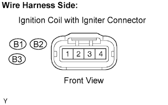
Disconnect the B1, B2 and/or B3 ignition coil with igniter connector.
-
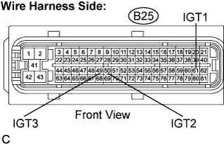
Disconnect the B25 ECM connector.
-
Measure the resistance.
Standard resistance (Check for open) Tester Connection Specified Condition Ignition coil (B1-3) - IGT1 (B25-61) Below 1 Ω Ignition coil (B2-3) - IGT2 (B25-50) Below 1 Ω Ignition coil (B3-3) - IGT3 (B25-49) Below 1 Ω Standard resistance (Check for short) Tester Connection Specified Condition Ignition coil (B1-3) or IGT1 (B25-61) - Body ground 10 kΩ or higher Ignition coil (B2-3) or IGT2 (B25-50) - Body ground 10 kΩ or higher Ignition coil (B3-3) or IGT3 (B25-49) - Body ground 10 kΩ or higher -
Reconnect the ignition coil with igniter connector.
-
Reconnect the ECM connector.
NG
REPAIR OR REPLACE HARNESS AND CONNECTOR
OK 
REPLACE IGNITION COIL W/IGNITOR
-
-
INSPECT ECM TERMINAL VOLTAGE (#1, #2 OR #3)
-
Turn the ignition switch to ON.
-
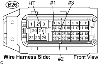
Measure the voltage between the terminals of the E20 ECM connector.
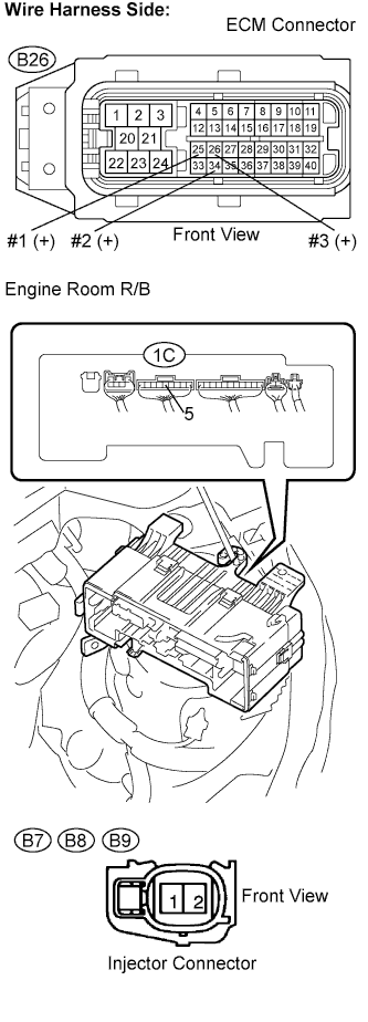
Standard voltage Tester Connection Specified Condition #1 (B26-25) - E1 (B26-24) 9 to 14 V #2 (B26-34) - E1 (B26-24) 9 to 14 V #3 (B26-26) - E1 (B26-24) 9 to 14 V
OK
INSPECT FUEL INJECTOR (INJECTION AND INJECTION VOLUME) Click here
NG
-
-
INSPECT FUEL INJECTOR (RESISTANCE)
-
Measure the resistance of the injector of the misfiring cylinder Click here.
Standard Resistance 11.6 to 12.4 Ω at 20 °C (68°F)
NG
REPLACE FUEL INJECTOR
OK
-
-
CHECK HARNESS AND CONNECTOR (INJECTOR - ECM, INJECTOR - EFI RELAY)
-
Check the harness and connectors between the injector and ECM.
-
Disconnect the B7, B8 and/or B9 injector connectors.
-
Disconnect the B26 ECM connector.
-
Measure the resistance.
Standard resistance (Check for open) Tester Connection Specified Condition Injector (B7-1) - #1 (B26-25) Below 1 Ω Injector (B8-1) - #2 (B26-34) Below 1 Ω Injector (B9-1) - #3 (B26-26) Below 1 Ω Standard resistance (Check for open) Tester Connection Specified Condition Injector (B7-1) or #1 (B26-25) - Body ground 10 kΩ or higher Injector (B8-1) or #2 (B26-34) - Body ground 10 kΩ or higher Injector (B9-1) or #3 (B26-26) - Body ground 10 kΩ or higher -
Reconnect the ECM connector.
-
-
Check the harness and connectors between the injector and EFI relay.
-
Disconnect the B7, B8 and/or B9 injector connectors.
-
Remove the engine room R/B.
-
Remove the engine room R/B lower cover.
-
Measure the resistance.
Standard resistance (Check for open) Tester Connection Specified Condition Injector (B7-2) - Engine room R/B (1C-5) Below 1 Ω Injector (B8-2) - Engine room R/B (1C-5) Below 1 Ω Injector (B9-2) - Engine room R/B (1C-5) Below 1 Ω Standard resistance (Check for open) Tester Connection Specified Condition Injector (B7-2) or Engine room R/B (1C-5) - Body ground 10 kΩ or higher Injector (B8-2) or Engine room R/B (1C-5) - Body ground 10 kΩ or higher Injector (B9-2) or Engine room R/B (1C-5) - Body ground 10 kΩ or higher -
Reconnect the injector connector.
-
Reinstall the engine room R/B.
-
NG
REPAIR OR REPLACE HARNESS AND CONNECTOR
OK
-
-
INSPECT FUEL INJECTOR (INJECTION AND INJECTION VOLUME)
-
Measure the injection volume of the injector of the misfiring cylinder Click here.
Standard 47 to 58 mm3 (2.87 to 3.54 cu in.) in 15 seconds
NG
REPLACE FUEL INJECTOR
OK
-
-
CHECK CYLINDER COMPRESSION PRESSURE
-
Inspect the cylinder compression pressure of the misfiring cylinder Click here.
Standard Minimum pressure 1,079 kPa (11.0 kgf/cm2, 156 psi) Difference between each cylinder 147 kPa (1.5 kgf/cm2, 21 psi)
NG
CHECK ENGINE TO DETERMINE CAUSE OF LOW COMPRESSION
OK
-
-
CHECK VALVE CLEARANCE
-
Inspect the valve clearance of the misfiring cylinder Click here.
Standard (cold) Intake 0.145 to 0.235 mm (0.00571 to 0.00925 in.) Exhaust 0.275 to 0.365 mm (0.01083 to 0.01437 in.)
NG
ADJUST VALVE CLEARANCE
OK
-
-
CHECK OUTPUT DTC (REFER TO RESULT OF STEP 3)
Tech Tips
Read the output DTCs and proceed to the appropriate step shown in the table below.
Result Number of Misfire Cylinder DTC Proceed To 1 DTC (other than DTC P0300) A 2 DTCs or more (other than DTC P0300) B
B
GO TO "CHECK FOR INTERMITTENT PROBLEMS"
A
-
CHECK VALVE TIMING
-
Inspect the valve timing Click here.
OK The matchmarks of the crankshaft pulley and camshaft pulley are aligning.
NG
ADJUST VALVE TIMING
OK
-
-
CHECK FUEL PRESSURE
-
Inspect the fuel pressure Click here.
Standard 304 to 343 kPa (3.1 to 3.5 kgf/cm2, 44.1 to 49.7 psi)
NG
REPAIR OR REPLACE FUEL SYSTEM
OK
-
-
READ VALUE USING VACUUM SENSOR (INTAKE AIR TEMPERATURE AND MANIFOLD ABSOLUTE PRESSURE)
-
Connect the intelligent tester to the DLC3.
-
Turn the ignition switch to ON.
-
Check the intake air temperature.
-
On the intelligent tester, select the following menu items: Powertrain / Engine and ECT / Data List / Intake Air.
-
Read the value.
Standard Equivalent to the ambient air temperature.
-
-
Check the mass air flow rate.
-
On the intelligent tester, select the following menu items: Powertrain / Engine and ECT / Data List / MAP
-
Read the values.
Standard Condition Manifold absolute pressure (kPa) Ignition switch ON (do not start engine) 50 to 115 Idling 25 to 45 Revving up without load (2,500 rpm) 20 to 45
-
NG
REPLACE MANIFOLD ABSOLUTE PRESSURE SENSOR
OK
-
-
READ VALUE USING ENGINE COOLANT TEMPERATURE SENSOR
-
Connect the intelligent tester to the DLC3.
-
Turn the ignition switch to ON and turn the intelligent tester ON.
-
Select the following menu items: Powertrain / Engine and ECT / Date List / Coolant Temp.
-
Read the Coolant Temp. value when the engine is cold and warmed up.
Standard Engine coolant temperature when the engine is cold Same as the ambient temperature. Engine coolant temperature when the engine is warmed up 75° to 95°C (167° to 203 °F)
NG
REPLACE ENGINE COOLANT TEMPERATURE SENSOR
OK
-
-
CHECK OUTPUT DTCS (REFER TO RESULT OF STEP 3)
Tech Tips
Read the output DTCs and proceed to the appropriate step shown in the table below.
Result Number of Misfire Cylinder DTC Proceed To 1 DTC (other than DTC P0300) A 2 DTCs or more (other than DTC P0300) B
B
CHECK SPARK PLUG Click here
A
GO TO "CHECK FOR INTERMITTENT PROBLEMS"