SFI SYSTEM (w/ Electronic Throttle Control System), Diagnostic DTC:P0261, P0262, P0264, P0265, P0267, P0268

| DTC Code | DTC Name |
|---|---|
| P0261 | Cylinder 1 Injector Circuit Low |
| P0262 | Cylinder 1 Injector Circuit High |
| P0264 | Cylinder 2 Injector Circuit Low |
| P0265 | Cylinder 2 Injector Circuit High |
| P0267 | Cylinder 3 Injector Circuit Low |
| P0268 | Cylinder 3 Injector Circuit High |
DESCRIPTION
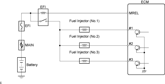
The injectors are installed in the intake manifold, and inject fuel into the cylinders based on the signals from the ECM.
| DTC No. | DTC Detection Condition | Trouble Area |
|---|---|---|
| P0261 P0264 P0267 |
Open or short to GND in injector circuit (3 trip detection logic) |
|
| P0262 P0265 P0268 |
Short in power source circuit (3 trip detection logic) |
|
Tech Tips
-
These DTCs are detected when the engine idles for approximately 15 seconds.
-
If DTC P0261 or P0262 is displayed, check No.1 injector circuit.
-
If DTC P0264 or P0265 is displayed, check No.2 injector circuit.
-
If DTC P0267 or P0268 is displayed, check No.3 injector circuit.
WIRING DIAGRAM
INSPECTION PROCEDURE
Note
After replace the ECM, perform electronic throttle learning Click here.
Tech Tips
Read freeze frame data using the intelligent tester. The ECM records vehicle and driving condition information as freeze frame data the moment a DTC is stored. When troubleshooting, freeze frame data can help determine if the vehicle was moving or stationary, if the engine was warmed up or not, if the air-fuel ratio was lean or rich, and other data from the time the malfunction occurred.
PROCEDURE
-
CHECK HARNESS AND CONNECTOR (ECM - INJECTOR)
-
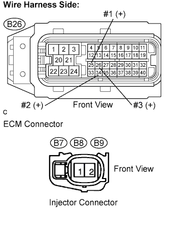
Disconnect the B7, B8 and/or B9 injector connectors.
-
Disconnect the B26 ECM connector.
-
Measure the resistance.
Standard resistance (Check for open) Tester Connection Specified Condition #1 (B26-25) - Injector (B7-1) Below 1 Ω #2 (B26-34) - Injector (B8-1) Below 1 Ω #3 (B26-26) - Injector (B9-1) Below 1 Ω Standard resistance (Check for short) Tester Connection Specified Condition #1 (B26-25) or Injector (B7-1) - Body ground 10kΩ or higher #2 (B26-34) or Injector (B8-1) - Body ground 10kΩ or higher #3 (B26-26) or Injector (B9-1) - Body ground 10kΩ or higher -
Reconnect the injector connector.
-
Reconnect the ECM connector.
NG 
REPAIR OR REPLACE HARNESS AND CONNECTOR
OK 
-
-
INSPECT FUEL INJECTOR (RESISTANCE)
-
Inspect the injector resistance.
-
Using an ohmmeter, measure the resistance between the terminals.
Standard resistance 1.3 to 14.2 Ω at 20°C (68°F)
-
NG
REPLACE FUEL INJECTOR
OK 
REPLACE ECM
-