SFI SYSTEM (w/ Electronic Throttle Control System), Diagnostic DTC:P0171, P0172

| DTC Code | DTC Name |
|---|---|
| P0171 | System Too Lean (Bank 1) |
| P0172 | System Too Rich (Bank 1) |
DESCRIPTION
The fuel trim relates to the feedback compensation value, not to the basic injection time. The fuel trim includes the short-term fuel trim and the long-term fuel trim.
The short-term fuel trim is the short-term fuel compensation used to maintain the air-fuel ratio at its ideal theoretical value. The signal from the heated oxygen sensor indicates whether the air-fuel ratio is rich or lean compared to the ideal theoretical value, triggering a reduction in the fuel volume if the air-fuel ratio is rich, and an increase in the fuel volume if it is lean.
The long-term fuel trim is the overall fuel compensation in order to balance the short-term fuel trim for a continual deviation from the central value by individual engine differences, operating environment and age deterioration.
If both the short-term fuel trim and the long-term fuel trim are lean or rich beyond the standard level, it is detected as a malfunction in the SFI system. The ECM illuminates the MIL and sets a DTC.
| DTC No. | DTC Detection Condition | Trouble Area |
|---|---|---|
| P0171 | When air-fuel ratio feedback is stable after warming up engine, fuel trim is considerably in error on lean side (3 trip detection logic) |
|
| P0172 | When air-fuel ratio feedback is stable after warming up engine, fuel trim is considerably in error on rich side (3 trip detection logic) |
|
CAUTION:
Strictly observe the traffic laws when performing the confirmation driving pattern.
Tech Tips
-
These DTCs are detected when the vehicle is driven for approximately 20 minutes at a constant vehicle speed of between 80 km/h (50 mph) and 110 km/h (70 mph) with the transmission gear selector lever in the 5th position (a malfunction is detected if the learning value of the driving range deviates by 25%).
-
When DTC P0171 is set, the actual air-fuel ratio is lean. When DTC P0172 is set, the actual air-fuel ratio is rich.
-
If the vehicle runs out of fuel, the air-fuel ratio is lean and DTC P0171 may be set. The MIL then illuminates.
-
If the total of the short-term fuel trim value and long-term fuel trim value is within 20%, the system functions normally.
-
When the air-fuel learning value is 1.23 or more, DTC P0171 will be set.
-
When the air-fuel learning value is 0.77 or less, DTC P0172 will be set.
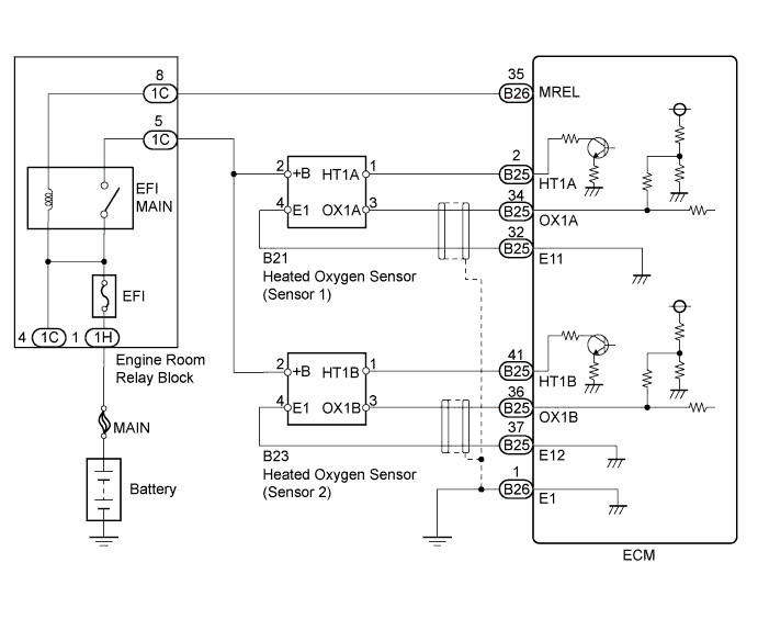
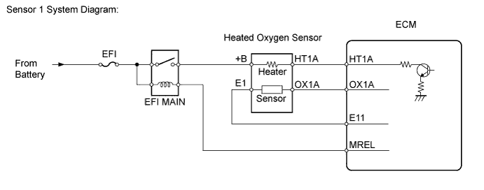
WIRING DIAGRAM
INSPECTION PROCEDURE
Note
Inspect the fuses for circuits related to this system before performing the following inspection procedure.
Tech Tips
Read freeze frame data using the intelligent tester. The ECM records vehicle and driving condition information as freeze frame data the moment a DTC is stored. When troubleshooting, freeze frame data can help determine if the vehicle was moving or stationary, if the engine was warmed up or not, if the air-fuel ratio was lean or rich, and other data from the time the malfunction occurred.
PROCEDURE
-
CHECK OTHER DTC OUTPUT (IN ADDITION TO DTC P0171 AND P0172)
-
Connect the intelligent tester to the DLC3.
-
Turn the ignition switch to ON and turn the tester on.
-
Enter the following menus: Powertrain / Engine and ECT / DTC.
-
Read DTCs.
Result Result Proceed to P0171 or P0172 A P0171 or P0172 and other DTCs B Tech Tips
If any DTCs other than P0171 or P0172 are output, troubleshoot those DTCs first.
B 
GO TO DTC CHART Click here
A 
-
-
PERFORM ACTIVE TEST USING INTELLIGENT TESTER (INJECTION VOLUME)
-
Connect the intelligent tester to the DLC3.
-
Start the engine and turn the tester on.
-
Warm up the engine.
-
Run the engine at 2500 rpm for approximately 3 minutes.
-
Enter the following menus: Powertrain / Engine and ECT / Active Test / A/F Control.
-
Perform the A/F control operation with the engine in an idle condition (press the right or left button to charge the fuel injection volume).
-
Monitor the voltage output of the heated oxygen sensors (O2S B1 S1 and O2S B1 S2) displayed on the tester.
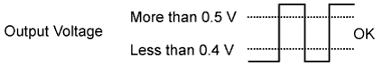
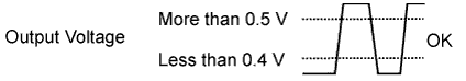
Result The heated oxygen sensor reacts in accordance with increases and decreases of the fuel injection volume: +25% = Rich output More than 0.5 V -12.5% = Lean output Less than 0.4 V Note
-
Sensor 1 (front sensor) has an output delay of a few seconds.
-
Sensor 2 (rear sensor) has maximum output delay of approximately 20 seconds.
Case Front HO2 Sensor (Sensor 1) Output Voltage Rear HO2 Sensor (Sensor 2) Output Voltage Main Suspected Trouble Area 1 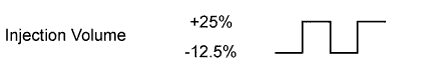
- 2 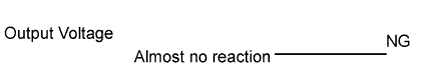
-
Heated oxygen sensor
3
-
Extremely rich or lean actual air-fuel ratio
-
Injector leak or blockage
-
Gas leakage from exhaust system
-
Ignition system
-
Fuel pressure
-
Manifold absolute pressure sensor
-
Engine coolant temperature sensor
The following procedure enables the technician to check and graph the voltage output of both the heated oxygen sensors.
To display the graph, enter the following menus: View / Line Graph.
Tech Tips
If the vehicle is short of fuel, the air-fuel ratio becomes lean and the heated oxygen sensor DTCs will be recorded, and then the MIL will illuminates.
Result Result Proceed to Case 1 C Case 2 B Case 3 A -
B 
CHECK HARNESS AND CONNECTOR (HEATED OXYGEN SENSOR (SENSOR 1) - ECM) Click here
C
PERFORM CONFIRMATION DRIVING PATTERN Click here
A
-
-
READ VALUE USING INTELLIGENT TESTER (MAP AND COOLANT TEMP)
-
Connect the intelligent tester to the DLC3.
-
Turn the ignition switch to ON and turn the tester on.
-
Enter the following menus: Powertrain / Engine and ECT / Data List / MAP and Coolant Temp.
-
Allow the engine to idle until the Coolant Temp. reaches 75°C (167°F).
-
Read the MAP value at idling and 2500 rpm.
Standard Ignition switch ON (do not start engine) 50 to 115 kPa Idling 25 to 45 kPa (shift lever in N and A/C OFF) 2500 rpm 20 to 45 kPa (shift lever in N and A/C OFF)
NG
REPLACE MANIFOLD ABSOLUTE PRESSURE SENSOR Click here
OK
-
-
READ VALUE USING INTELLIGENT TESTER (COOLANT TEMP)
-
Connect the intelligent tester to the DLC3.
-
Turn the ignition switch to ON and turn the tester on.
-
Enter the following menus: Powertrain / Engine and ECT / Data List / Coolant Temp.
-
Read the Coolant Temp value when the engine is cold and warmed up.
Standard Engine coolant temperature when the engine is cold: Same as the ambient temperature. Engine coolant temperature when the engine is warmed up: 75° to 95°C (167° to 203°F).
NG
REPLACE ENGINE COOLANT TEMPERATURE SENSOR Click here
OK
-
-
CHECK SPARK AND IGNITION
-
Check the spark Click here.
OK The spark occurs.
NG
REPAIR OR REPLACE IGNITION SYSTEM
OK
-
-
CHECK FOR EXHAUST GAS LEAK
-
Check for exhaust gas leakage.
OK No gas leak.
NG
REPAIR OR REPLACE EXHAUST GAS LEAKAGE POINT
OK
-
-
CHECK FUEL PRESSURE
-
Inspect the fuel pressure Click here.
Standard 304 to 343 kPa (3.1 to 3.5 kgf/cm2, 44.1 to 49.7 psi)
NG
REPAIR OR REPLACE FUEL SYSTEM
OK
-
-
INSPECT FUEL INJECTOR
-
Check the injection volume Click here.
Standard 47 to 58 mm3 (2.87 to 3.54 cu in.) in 15 seconds
NG
REPLACE FUEL INJECTOR Click here
OK
-
-
CHECK HARNESS AND CONNECTOR (HEATED OXYGEN SENSOR (SENSOR 1) - ECM)
-
Disconnect the heated oxygen sensor connector (sensor 1).
-
Disconnect the ECM connectors.
-
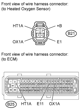
Measure the resistance according to the value(s) in the table below.
Standard Resistance (Check for Open) Tester Connection Condition Specified Condition B21-3 (OX1A) - B25-34 (OX1A) Always Below 1 Ω B21-1 (HT1A) - B25-2 (HT1A) Always Below 1 Ω B21-4 (E1) - B25-32 (E11) Always Below 1 Ω Standard Resistance (Check for Short) Tester Connection Condition Specified Condition B21-3 (OX1A) or B25-34 (OX1A) - Body ground Always 10 kΩ or higher B21-1 (HT1A) or B25-2 (HT1A) - Body ground Always 10 kΩ or higher -
Reconnect the heated oxygen sensor connector.
-
Reconnect the ECM connectors.
NG
REPAIR OR REPLACE HARNESS OR CONNECTOR
OK
-
-
REPLACE HEATED OXYGEN SENSOR (SENSOR 1)
-
Replace the heated oxygen sensor (sensor 1) Click here.
NEXT
-
-
PERFORM CONFIRMATION DRIVING PATTERN
-
Drive the vehicle for approximately 20 minutes at a vehicle speed between 80 km/h and 110 km/h (between 50 mph and 70 mph) with the transmission gear selector lever in the 5th position.
NEXT
-
-
CHECK IF DTC OUTPUT RECURS
-
Connect the intelligent tester to the DLC3.
-
Turn the ignition switch to ON and turn the tester on.
-
Enter the following menus: Powertrain / Engine and ECT / DTC / Pending.
-
Read DTCs.
Result Result Proceed to No output A P0171 or P0172 B
B
REPLACE ECM Click here
A 
END
-