SFI SYSTEM (w/ Electronic Throttle Control System), Diagnostic DTC:P2122, P2123, P2127, P2128

| DTC Code | DTC Name |
|---|---|
| P2122 | Throttle / Pedal Position Sensor / Switch "D" Circuit Low Input |
| P2123 | Throttle / Pedal Position Sensor / Switch "D" Circuit High Input |
| P2127 | Throttle / Pedal Position Sensor / Switch "E" Circuit Low Input |
| P2128 | Throttle / Pedal Position Sensor / Switch "E" Circuit High Input |
DESCRIPTION
Tech Tips
-
This is the repair procedure for the accelerator pedal position sensor.
-
This electrical throttle system does not use a throttle cable.
-
This accelerator pedal position sensor is a non-contact type.
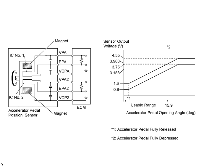
The accelerator pedal position sensor is mounted on the accelerator pedal and detects the opening angle of the accelerator pedal. Since this sensor is electronically controlled with Hall-effect elements, accurate control and reliability can be obtained. It has 2 sensors to detect the accelerator position and a malfunction of the accelerator position sensor.
In the accelerator pedal position sensor, the voltage applied to pedal terminals VPA and VPA2 of the ECM changes between 0 V and 5 V in proportion to the opening angle of the accelerator pedal. The VPA is a signal to indicate the actual accelerator pedal opening angle which is used for the engine control, and the VPA2 is a signal to indicate the information about the opening angle which is used for detecting malfunctions. The ECM judges the current opening angle of the accelerator pedal using signals from terminals VPA and VPA2, and the ECM controls the throttle motor based on these signals.
| DTC No. | DTC Detection Condition (All of following are 1 trip detection logic) |
Trouble Area |
|---|---|---|
| P2122 | VPA is 0.7 V or less for 0.5 sec. or more when VPA2 output indicate accelerator pedal is opened |
|
| P2123 |
|
|
| P2127 | VPA2 is 0.65 V or less for 0.5 sec. or more when VPA output indicates accelerator pedal is opened |
|
| P2128 | VPA2 is 4.03 V or more for 2.0 sec. or more |
|
Tech Tips
Detection for P2122, P2123, P2127 and P2128 is performed when the ignition switch is ON or the engine is running.
WIRING DIAGRAM
INSPECTION PROCEDURE
Note
After replacing the ECM, perform electronic throttle learning Click here.
Tech Tips
Read freeze frame data using the intelligent tester. The ECM records vehicle and driving condition information as freeze frame data the moment a DTC is stored. When troubleshooting, freeze frame data can help determine if the vehicle was moving or stationary, if the engine was warmed up or not, if the air-fuel ratio was lean or rich, and other data from the time the malfunction occurred.
PROCEDURE
-
CHECK HARNESS AND CONNECTOR (ACCELERATOR PEDAL POSITION SENSOR - ECM)
-
Disconnect accelerator pedal position sensor connector.
-
Disconnect the ECM connector.
-
Measure the resistance according to the value(s) in the table below.
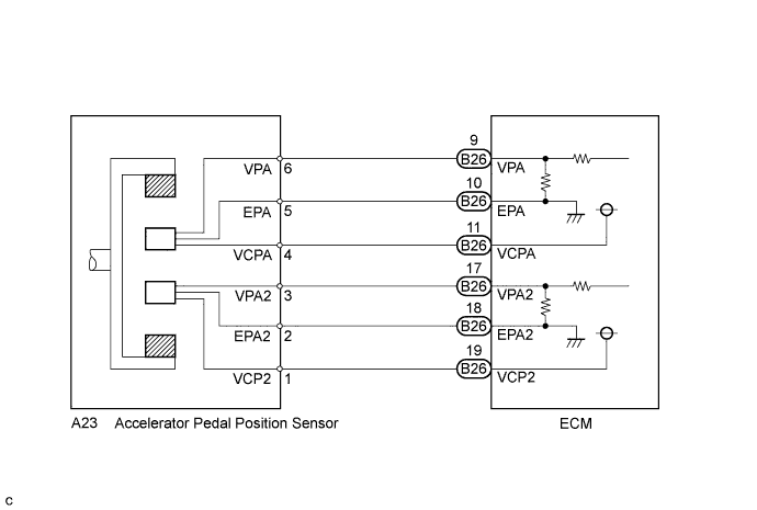
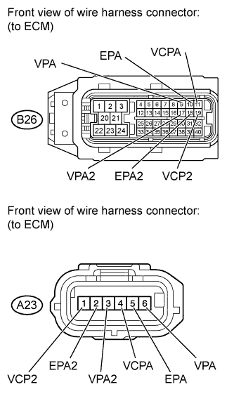
Standard Resistance (Check for Open) Tester Connection Condition Specified Condition B26-11 (VCPA) - A23-4 (VCPA) Always Below 1 Ω B26-9 (VPA) - A23-6 (VPA) Always Below 1 Ω B26-10 (EPA) - A23-5 (EPA) Always Below 1 Ω B26-19 (VCP2) - A23-1 (VCP2) Always Below 1 Ω B26-17 (VPA2) - A23-3 (VPA2) Always Below 1 Ω B26-18 (EPA2) - A23-2 (EPA2) Always Below 1 Ω Standard Resistance (Check for Short) Tester Connection Condition Specified Condition B26-11 (VCPA) or 23-4 (VCPA) - Body ground Always 10 kΩ or higher B26-9 (VPA) or A23-6 (VPA) - Body ground Always 10 kΩ or higher B26-10 (EPA) or A23-5 (EPA) - Body ground Always 10 kΩ or higher B26-19 (VCP2) - A23-1 (VCP2) - Body ground Always 10 kΩ or higher B26-17 (VPA2) - A23-3 (VPA2) - Body ground Always 10 kΩ or higher B26-18 (EPA2) - A23-2 (EPA2) - Body ground Always 10 kΩ or higher -
Reconnect the accelerator pedal position sensor connector.
-
Reconnect the ECM connector.
NG 
REPAIR OR REPLACE HARNESS OR CONNECTOR
OK 
-
-
CHECK TERMINAL VOLTAGE (ACCELERATOR PEDAL POSITION SENSOR CONNECTOR)
-
Disconnect the accelerator pedal position sensor connector.
-
Measure the voltage according to the value(s) in the table below.
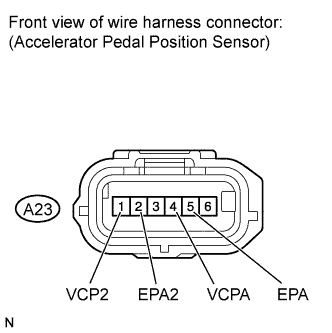
Tester Connection Switch Condition Specified Condition A23-1 (VCP2) - A23-2 (EPA2) Ignition switch ON 4.5 to 5.5 V A23-4 (VCPA) - A23-5 (EPA) Ignition switch ON 4.5 to 5.5 V -
Reconnect the accelerator pedal position sensor connector.
-
Clear the DTC Click here.
NG
REPLACE ECM Click here
OK 
REPLACE ACCELERATOR PEDAL Click here
-