SFI SYSTEM (w/ Electronic Throttle Control System), Diagnostic DTC:P0136, P0140

| DTC Code | DTC Name |
|---|---|
| P0136 | Oxygen Sensor Circuit Malfunction (Bank 1 Sensor 2) |
| P0140 | Heated Oxygen Sensor Circuit No Activity Detected (Bank 1 Sensor 2) |
DESCRIPTION
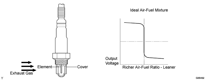
In order to obtain a high purification rate for the carbon monoxide (CO), hydrocarbon (HC) and nitrogen oxide (NOx) components in the exhaust gas, a Three-Way Catalytic Converter (TWC) is used. For the most efficient use of the TWC, the air-fuel ratio must be precisely controlled so that it is always close to the stoichiometric air-fuel ratio. The heated oxygen sensor has the characteristic whereby its output voltage changes suddenly in the vicinity of the stoichiometric air-fuel ratio. This is used to detect the oxygen concentration in the exhaust gas and provide the ECM with feedback to control the air-fuel ratio. When the air-fuel ratio becomes lean, the oxygen concentration in the exhaust gas increases. The heated oxygen sensor informs the ECM of the lean condition (low voltage, i.e. less than 0.45 V). When the air-fuel ratio is richer than the stoichiometric air-fuel level, the oxygen concentration in the exhaust gas is reduced. And the heated oxygen sensor informs the ECM of the rich condition (high voltage, i.e. more than 0.45 V). The ECM judges by the voltage output of the heated oxygen sensor whether the air-fuel ratio is rich or lean and controls the injection time accordingly. If a malfunction of the heated oxygen sensor causes an output of abnormal voltage, the ECM is unable to perform accurate air-fuel ratio control. The heated oxygen sensor includes a heater which heats the zirconia element. The heater is controlled by the ECM. When the intake air volume is low (the temperature of the exhaust gas is low), a current flows to the heater in order to heat the sensor for accurate oxygen concentration detection.
| DTC No. | DTC Detection Condition | Trouble Area |
|---|---|---|
| P0136 | Heated oxygen sensor (sensor 2) output voltage is remains 0.06 V or less for 90 seconds or more. |
|
| P0140 | Heated oxygen sensor (sensor 2) voltage is between 0.4 V and 0.52 V continuously for 600 seconds (3 trip detection logic) |
|
| P0140 | ECM determines that internal resistance of heated oxygen sensor (sensor 2) is 40kΩ or more after warm-up (3 trip detection logic) |
|
Tech Tips
-
The internal resistance of the heated oxygen sensor (sensor 2) cannot be measured using a tester.
-
Sensor 2 refers to the sensor farthest away from the engine assembly.
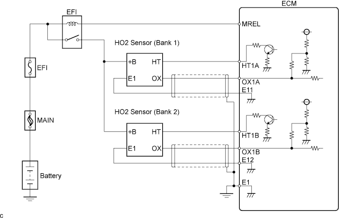
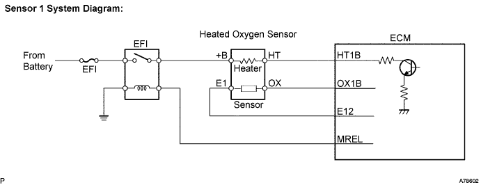
WIRING DIAGRAM
CONFIRMATION DRIVING PATTERN
CAUTION:
Strictly observe the traffic laws when performing the confirmation driving pattern.
Tech Tips
-
DTC P0136 is detected when the vehicle is driven at a vehicle speed of 70 to 110 km/h (43 to 68 mph) with the shift lever in the 5th position for 90 seconds or more after driving at an average speed of approximately 50 km/h (31 mph) in the city for approximately 30 minutes from cold start (engine coolant when engine star is less than 40 °C (104°F)).
-
DTC P140 is detected when the vehicle is driven at an average vehicle speed of approximately 50 km/h (31 mph) in the city for approximately 30 minutes.
INSPECTION PROCEDURE
PROCEDURE
-
CHECK HARNESS AND CONNECTOR (HEATED OXYGEN SENSOR (SENSOR 2) - ECM)
-
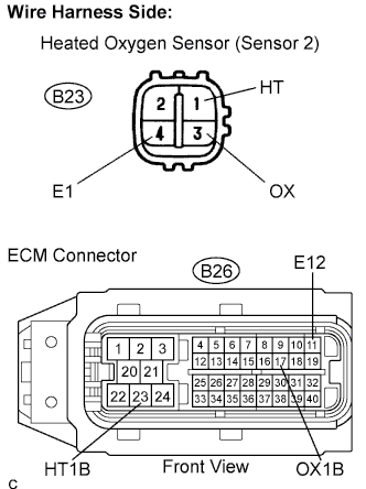
Disconnect the B23 heated oxygen sensor connector (sensor 2).
-
Disconnect the B26 ECM connector.
-
Measure the resistance.
Standard resistance (Check for open) Tester Connection Specified Condition OX (B23-3) - OX1B (B26-17) Below 1 Ω E1 (B23-4) - E12 (B26-11) Below 1 Ω Standard resistance (Check for short) Tester Connection Specified Condition OX (B23-3) or OX1B (B26-17) - Body ground 10 kΩ or higher -
Reconnect the heated oxygen sensor connector.
-
Reconnect the ECM connector.
NG 
REPAIR OR REPLACE HARNESS AND CONNECTOR
OK 
REPLACE HEATED OXYGEN SENSOR (SENSOR 2)
-