SFI SYSTEM (w/ Electronic Throttle Control System), Diagnostic DTC:P0135

| DTC Code | DTC Name |
|---|---|
| P0135 | Oxygen (A/F) Sensor Heater Circuit (Bank 1 Sensor 1) |
DESCRIPTION
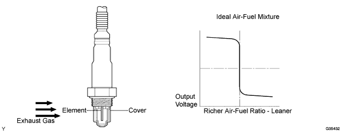
In order to obtain a high purification rate for the carbon monoxide (CO), hydrocarbon (HC) and nitrogen oxide (NOx) components in the exhaust gas, a Three-Way Catalytic Converter (TWC) is used. For the most efficient use of the TWC, the air-fuel ratio must be precisely controlled so that it is always close to the stoichiometric air-fuel ratio. The heated oxygen sensor has the characteristic whereby its output voltage changes suddenly in the vicinity of the stoichiometric air-fuel ratio. This is used to detect the oxygen concentration in the exhaust gas and provide the ECM with feedback to control the air-fuel ratio. When the air-fuel ratio becomes lean, the oxygen concentration in the exhaust gas increases. The heated oxygen sensor informs the ECM of the lean condition (low voltage, i.e. less than 0.45 V). When the air-fuel ratio is richer than the stoichiometric air-fuel level, the oxygen concentration in the exhaust gas is reduced. And the heated oxygen sensor informs the ECM of the rich condition (high voltage, i.e. more than 0.45 V). The ECM judges by the voltage output of the heated oxygen sensor whether the air- fuel ratio is rich or lean and controls the injection time accordingly. If a malfunction of the heated oxygen sensor causes an output of abnormal voltage, the ECM is unable to perform accurate air-fuel ratio control. The heated oxygen sensor includes a heater which heats the zirconia element. The heater is controlled by the ECM. When the intake air volume is low (the temperature of the exhaust gas is low), a current flows to the heater in order to heat the sensor for accurate oxygen concentration detection.
Tech Tips
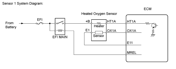
The ECM provides a pulse width modulated control circuit to adjust current through the heater. The heated oxygen sensor heater circuit uses a relay on the +B side of the circuit.
| DTC No. | DTC Detection Condition | Trouble Area |
|---|---|---|
| P0135 | Open or short of heated oxygen sensor (sensor 1) heater or related circuit (3 trip detection logic). |
|
Tech Tips
-
DTC P0135 is detected when the engine idles for 1 minute.
-
Sensor 1 refers to the sensor mounted in front of the Three-Way Catalytic Converter (TWC) and located near the engine assembly.
-
Sensor 2 refers to the sensor mounted behind the TWC and located far from the engine assembly.
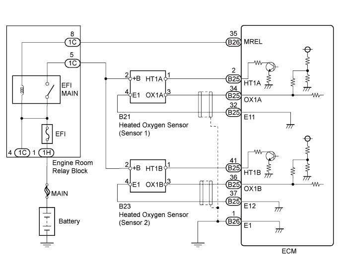
WIRING DIAGRAM
INSPECTION PROCEDURE
Note
After replacing the ECM, perform electronic throttle learning Click here.
Inspect the fuses for circuits related to this system before performing the following inspection procedure.
Tech Tips
Read freeze frame data using the intelligent tester. The ECM records vehicle and driving condition information as freeze frame data the moment a DTC is stored. When troubleshooting, freeze frame data can help determine if the vehicle was moving or stationary, if the engine was warmed up or not, if the air-fuel ratio was lean or rich, and other data from the time the malfunction occurred.
PROCEDURE
-
INSPECT HEATED OXYGEN SENSOR (SENSOR RESISTANCE)
-
Disconnect the heated oxygen sensor connector (sensor 1).
-
Measure the resistance according to the value(s) in the table below.
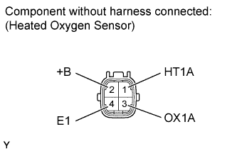
Standard Resistance Tester Connection Condition Specified Condition 1 (HT1A) - 2 (+B) 25°C (77°F) 6 to 14 Ω 1 (HT1A) - 4 (E1) Always 10 kΩ or higher
NG 
REPLACE HEATED OXYGEN SENSOR (SENSOR 1) Click here
OK 
-
-
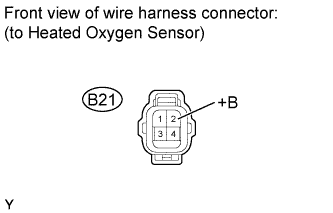
CHECK TERMINAL VOLTAGE (+B OF HEATED OXYGEN SENSOR)
-
Disconnect the heated oxygen sensor connector (sensor 1).
-
Measure the voltage according to the value(s) in the table below.
Standard Voltage Tester Connection Switch Condition Specified Condition B21-2 (+B) - Body ground Ignition switch ON 11 to 14 V -
Reconnect the heated oxygen sensor.
Result Result Proceed to Outside standard range A Within standard range B
B 
CHECK HARNESS AND CONNECTOR (HEATED OXYGEN SENSOR - ECM - EFI MAIN RELAY) Click here
A
-
-
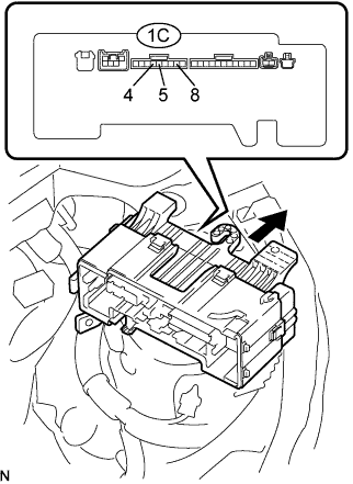
INSPECT ENGINE ROOM RELAY BLOCK (EFI MAIN RELAY)
-
Remove the engine room relay block.
-
Remove the engine room relay block lower cover.
-
Disconnect the 5 connectors from the engine room relay block.
-
Measure the EFI main relay resistance.
Standard Resistance Tester Connection Condition Specified Condition 1C-4 - 1C-5 When battery voltage absent 10 kΩ or higher 1C-4 - 1C-5 When battery voltage applied to terminals 1C-4 - 1C-8 Below 1 Ω -
Reinstall the engine room relay block.
NG
REPLACE ENGINE ROOM RELAY BLOCK
OK
-
-
CHECK HARNESS AND CONNECTOR (HEATED OXYGEN SENSOR - ECM - EFI MAIN RELAY)
-
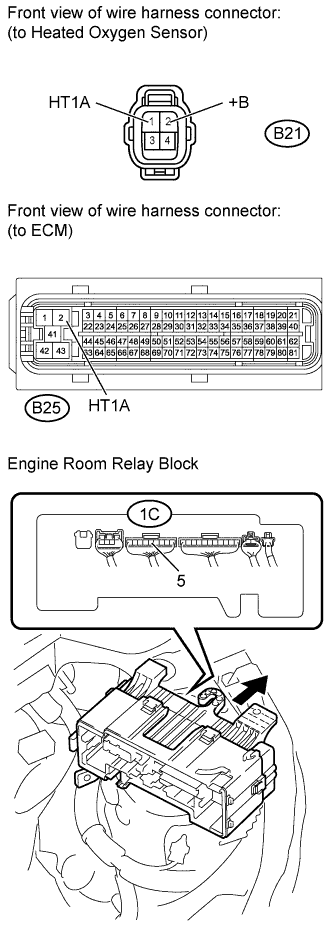
Check the harness and the connectors between the ECM and the heated oxygen sensor.
-
Disconnect the heated oxygen sensor connector (sensor 1).
-
Disconnect the ECM connector.
-
Measure the resistance according to the value(s) in the table below.
Standard Resistance (Check for Open) Tester Connection Condition Specified Condition B21-1 (HT1A) - B25-2 (HT1A) Always Below 1 Ω Standard Resistance (Check for Short) Tester Connection Condition Specified Condition B21-1 (HT1A) or B25-2 (HT1A) - Body ground Always 10 kΩ or higher -
Reconnect the ECM connector.
-
-
Check the harness and the connectors between the heated oxygen sensor and EFI main relay.
-
Remove the engine room relay block.
-
Remove the engine room relay block lower cover.
-
Measure the resistance according to the value(s) in the table below.
Standard Resistance (Check for Open) Tester Connection Condition Specified Condition B21-2 (+B) - 1C-5 Always Below 1 Ω Standard Resistance (Check for Short) Tester Connection Condition Specified Condition B21-2 (+B) or 1C-5 - Body ground Always 10 kΩ or higher -
Reconnect the heated oxygen sensor connector.
-
Reinstall the engine room relay block.
-
NG
REPAIR OR REPLACE HARNESS OR CONNECTOR
OK
-
-
CHECK WHETHER DTC OUTPUT RECURS
-
Start the engine.
-
Allow the engine to idle for 1 minute or more.
-
Connect the intelligent tester to the DLC3.
-
Enter the following menus: Powertrain / Engine and ECT / DTC / Pending.
Result Result Proceed to No output A P0135 B
B
REPLACE ECM Click here
A 
CHECK FOR INTERMITTENT PROBLEMS Click here
-