SFI SYSTEM (w/ Electronic Throttle Control System), Diagnostic DTC:P0133

| DTC Code | DTC Name |
|---|---|
| P0133 | Oxygen (A/F) Sensor Circuit Slow Response (Bank 1 Sensor 1) |
DESCRIPTION
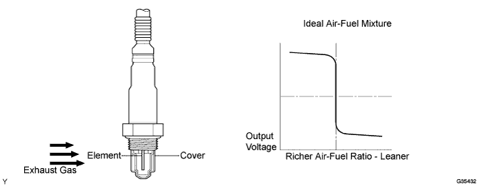
In order to obtain a high purification rate for the carbon monoxide (CO), hydrocarbon (HC) and nitrogen oxide (NOx) components in the exhaust gas, a Three-Way Catalytic Converter (TWC) is used. For the most efficient use of the TWC, the air-fuel ratio must be precisely controlled so that it is always close to the stoichiometric air-fuel ratio. The heated oxygen sensor has the characteristic whereby its output voltage changes suddenly in the vicinity of the stoichiometric air-fuel ratio. This is used to detect the oxygen concentration in the exhaust gas and provide the ECM with feedback to control the air-fuel ratio. When the air-fuel ratio becomes lean, the oxygen concentration in the exhaust gas increases. The heated oxygen sensor informs the ECM of the lean condition (low voltage, i.e. less than 0.45 V). When the air-fuel ratio is richer than the stoichiometric air-fuel level, the oxygen concentration in the exhaust gas is reduced. And the heated oxygen sensor informs the ECM of the rich condition (high voltage, i.e. more than 0.45 V). The ECM judges by the voltage output of the heated oxygen sensor whether the air-fuel ratio is rich or lean and controls the injection time accordingly. If a malfunction of the heated oxygen sensor causes an output of abnormal voltage, the ECM is unable to perform accurate air-fuel ratio control. The heated oxygen sensor includes a heater which heats the zirconia element. The heater is controlled by the ECM. When the intake air volume is low (the temperature of the exhaust gas is low), a current flows to the heater in order to heat the sensor for accurate oxygen concentration detection.
| DTC No. | DTC Detection Condition | Trouble Area |
|---|---|---|
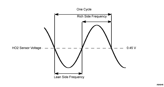
| P0133 | The response time of heated oxygen sensor's output voltage in one RICH-LEAN cycle is 3 seconds or more while the vehicle speed is between 60 to 100 km/h (37.5 to 62 mph) with the transmission position in the 5th position (3 trip detection logic). |
|
Tech Tips
RICH-LEAN cycle
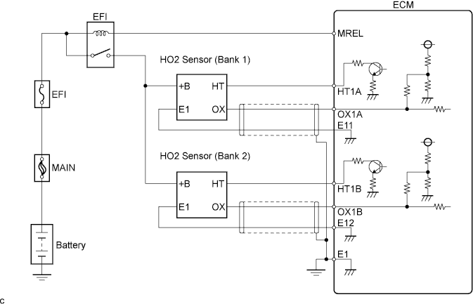
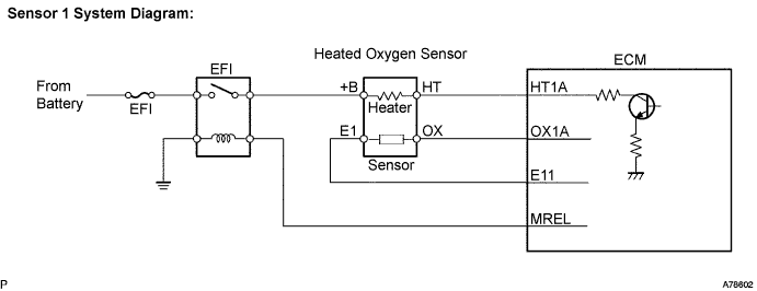
WIRING DIAGRAM
CONFIRMATION DRIVING PATTERN
Drive the vehicle at an average vehicle speed of approximately 50 km/h (31 mph) in the city for approximately 30 minutes, and then drive for 5 minutes or more at a vehicle speed between 60 to 100 km/h (37.5 to 62 mph) with the transmission gear selector lever in the 5th position (Engine speed is 1,800 to 3,200 rpm, engine load is 25 to 50 %).
INSPECTION PROCEDURE
Tech Tips
-
Read freeze frame data using the intelligent tester. The ECM records vehicle and driving condition information as freeze frame data the moment a DTC is stored. When troubleshooting, freeze frame data can help determine if the vehicle was moving or stationary, if the engine was warmed up or not, if the air-fuel ratio was lean or rich, and other data from the time the malfunction occurred.
-
A high heated oxygen sensor (sensor 1) voltage (0.5 V or more) could be caused by a rich air-fuel mixture. Check for conditions that would cause the engine to run rich.
-
A low heated oxygen sensor (sensor 1) voltage (0.4 V or less) could be caused by a lean air-fuel mixture. Check for conditions that would cause the engine to run lean.
PROCEDURE
-
CHECK OTHER DTC OUTPUT
-
Connect the intelligent tester to the DLC3.
-
Turn the ignition switch to ON and turn the intelligent tester ON.
-
Select the following menu items: Powertrain / Engine and ECT / DTC.
-
Read DTCs.
Result Display (DTC Output) Proceed To P0133 A P0133 and other DTCs B Tech Tips
If any DTCs other than P0133 are output, troubleshoot those DTCs first.
B 
GO TO DTC CHART
A 
-
-
PERFORM ACTIVE TEST USING INTELLIGENT TESTER (Control the Injection Volume for A/F Sensor)
-
Connect the intelligent tester to the DLC3.
-
Start the engine and turn the intelligent tester ON.
-
Warm up the engine.
-
Run the engine at 2,500 rpm for approximately 3 minutes.
-
On the intelligent tester, select the following menu items: Powertrain / Engine and ECT / Active Test / A/F Control.
-
Perform the A/F control operation with the engine in an idle condition (press the right or left button to charge the fuel injection volume).
-
Monitor the voltage output of the heated oxygen sensors (O2S B1S1 and O2S B1S2) displayed on the tester.
Result The heated oxygen sensor reacts in accordance with increases and decreases of the fuel injection volume: +25 % = Rich output More than 0.5 V -12.5 % = Lean output Less than 0.4 V Note
-
Sensor 1 (front sensor) has an output delay of a few seconds.
-
Sensor 2 (rear sensor) has maximum output delay of approximately 20 seconds.
Output voltage of heated oxygen sensor (sensor 1: front sensor) Output voltage of heated oxygen sensor (sensor 2: rear sensor) Mainly suspected trouble area Case 1 Injection volume
+25 %
-12.5 %

Injection volume
+25 %
-12.5 %
- Output voltage
More than 0.5 V
Less than 0.4 V

Output voltage
More than 0.5 V
Less than 0.4 V

Case 2 Injection volume
+25 %
-12.5 %
Injection volume
+25 %
-12.5 %
-
Heated oxygen sensor (Sensor 1)
Output voltage
Almost no reaction

Output voltage
More than 0.5 V
Less than 0.4 V
Case 3 Injection volume
+25 %
-12.5 %
Injection volume
+25 %
-12.5 %
-
Extremely rich or lean actual air-fuel ratio
-
Injector leakage or blockage
-
Gas leakage from exhaust system
-
Ignition system
-
Fuel pressure
-
Manifold absolute pressure sensor
-
Engine coolant temperature sensor
Output voltage
Almost no reaction
Output voltage
Almost no reaction
The following procedure enables the technician to check and graph the voltage output of both the heated oxygen sensors.
To display the graph, select the following menu items on the tester: View / Line Graph.
Tech Tips
If the vehicle is short of fuel, the air-fuel ratio becomes lean and the heated oxygen sensor DTCs will be recorded, and then the MIL will illuminates.
Result Result Proceed To Case 1 C Case 2 A Case 3 B -
B 
CHECK WHETHER MISFIRE OCCURS Click here
C
PERFORM CONFIRMATION DRIVING PATTERN Click here
A
-
-
CHECK HARNESS AND CONNECTOR (HEATED OXYGEN SENSOR (SENSOR 1) - ECM)
-
Disconnect the B21 heated oxygen sensor connector (sensor 1).
-
Disconnect the E19 and B26 ECM connectors.
-
Measure the resistance.
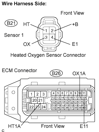
Standard resistance (check for open) Tester Connection Specified Condition OX (B21-3) - OX1A (B26-18) Below 1 Ω HT (B21-1) - HT1A (B26-21) Below 1 Ω E1 (B21-4) - E11 (B26-19) Below 1 Ω Standard resistance (check for short) Tester Connection Specified Condition OX (B21-3) or OX1A (B26-18) - Body ground 10 kΩ or higher HT (B21-1) or HT1A (B26-21) - Body ground 10 kΩ or higher -
Reconnect the heated oxygen sensor connector.
-
Reconnect the ECM connectors.
NG
REPAIR OR REPLACE HARNESS AND CONNECTOR
OK
-
-
REPLACE HEATED OXYGEN SENSOR (SENSOR 1)
NEXT
-
CHECK IF DTC OUTPUT RECURS
-
Connect the intelligent tester to the DLC3.
-
Turn the ignition switch to ON and turn the intelligent tester ON.
-
Clear the DTCs.
-
Perform CONFIRMATION DRIVING PATTERN.
-
Select the following menu items: Powertrain / Engine and ECT / DTC / Pending.
-
Read DTCs.
Result Display (DTC Output) Proceed To No output A P0133 B
B
CHECK WHETHER MISFIRE OCCURS Click here
A 
END
-
-
CHECK WHETHER MISFIRE OCCURS
-
Check the idling condition.
OK Rough idle does not occur.
NG
TROUBLESHOOT MISFIRE
OK
-
-
CHECK FUEL PRESSURE
-
Check the fuel pressure Click here.
Standard 304 to 343 kPa (3.1 to 3.5 kgf/cm2, 44.1 to 49.7 psi)
NG
REPAIR OR REPLACE FUEL SYSTEM
OK
-
-
INSPECT FUEL INJECTOR
-
Check the injection volume Click here.
Standard 47 to 58 mm3 (2.87 to 3.54 cu in.) in 15 seconds
NG
REPLACE FUEL INJECTOR
OK
CHECK FOR EXHAUST GAS LEAKS
-
-
PERFORM CONFIRMATION DRIVING PATTERN
Tech Tips
Clear all DTCs prior to performing the confirmation driving pattern.
NEXT
-
CHECK IF DTC OUTPUT RECURS
-
Connect the intelligent tester to the DLC3.
-
Turn the ignition switch to ON and turn the intelligent tester ON.
-
Select the following menu items: Powertrain / Engine and ECT / DTC / Pending.
-
Read DTCs.
Result Display (DTC Output) Proceed To P0133 A No output B
B
GO TO "CHECK FOR INTERMITTENT PROBLEMS"
A
REPLACE HEATED OXYGEN SENSOR (SENSOR 1)
-