SFI SYSTEM (w/ Electronic Throttle Control System), Diagnostic DTC:P0122, P0123, P0222, P0223

| DTC Code | DTC Name |
|---|---|
| P0122 | Throttle / Pedal Position Sensor / Switch "A" Circuit Low Input |
| P0123 | Throttle / Pedal Position Sensor / Switch "A" Circuit High Input |
| P0222 | Throttle / Pedal Position Sensor / Switch "B" Circuit Low Input |
| P0223 | Throttle / Pedal Position Sensor / Switch "B" Circuit High Input |
DESCRIPTION
Tech Tips
This ETC (Electrical Throttle Control System) does not use a throttle cable.
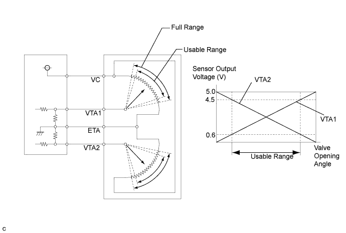
The Throttle Position (TP) sensor is mounted on the throttle body, and detects the opening angle of the throttle valve.
The TP sensor has two sensor circuits which each transmits a signal, VTA1 and VTA2. VTA1 is used to detect the throttle valve angle and VTA2 is used to detect malfunctions in VTA1. The sensor signal voltages vary between 0 V and 5 V. The VTA1 sensor signal voltage vary in proportion to the throttle valve opening angle, and are transmitted to the VTA terminals of the ECM.
As the valve closes, the VTA1 sensor output voltage decreases and as the valve opens, the VTA1 sensor output voltage increases. The ECM calculates the throttle valve opening angle according to these signals and controls the throttle actuator in response to driver inputs.
| DTC No. | DTC Detection Condition | Trouble Area |
|---|---|---|
| P0122 | Output voltage of VTA1 0.2 V or less for 0.14 seconds or more. (1 trip detection logic) |
|
| P0123 | Output voltage of VTA1 4.6 V or more (1 trip detection logic) |
|
| P0222 | Output voltage of VTA2 0.156 V or less when engine speed is 1,200 rpm or moer for 0.14 seconds or more. (1 trip detection logic) |
|
| P0223 | Output voltage of VTA2 4.883 V or more (1 trip detection logic) |
|
Tech Tips
-
Detection is always being performed for P0122, P0123 and P0223 when the ignition switch is in the ON position or the engine is running.
-
Detection for P0222 is performed when the engine speed is 1,200 rpm or greater.
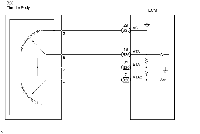
WIRING DIAGRAM
INSPECTION PROCEDURE
Note
After replace the ECM and/or throttle body, perform electronic throttle learning Click here.
Tech Tips
Read freeze frame data using the intelligent tester. The ECM records vehicle and driving condition information as freeze frame data the moment a DTC is stored. When troubleshooting, freeze frame data can help determine if the vehicle was moving or stationary, if the engine was warmed up or not, if the air-fuel ratio was lean or rich, and other data, from the time the malfunction occurred.
PROCEDURE
-
CHECK HARNESS AND CONNECTOR (THROTTLE BODY - ECM)
-
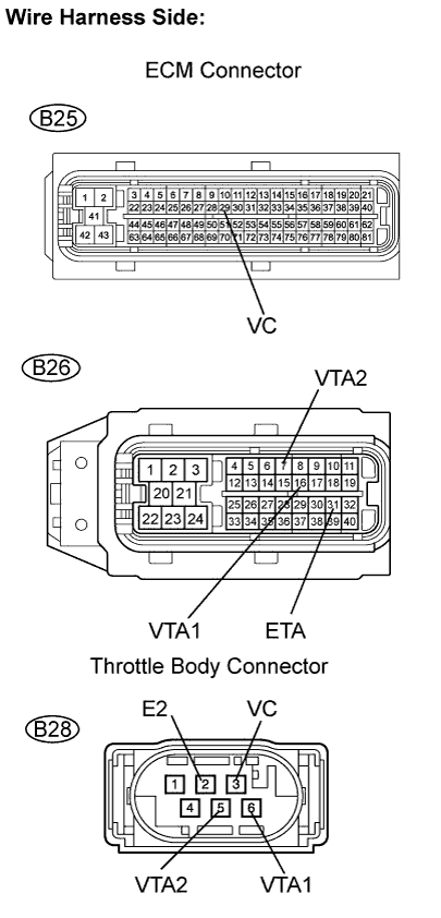
Disconnect the B28 throttle body connector.
-
Disconnect the B25 and B26 ECM connectors
-
Measure the resistance between the throttle body connector and ECM connector.
Standard resistance (Check for open) Tester Connection Specified Condition VC (B28-3) - VC (B25-29) Below 1 Ω VTA1 (B28-6) - VTA1 (B26-16) Below 1 Ω VTA2 (B28-5) - VTA2 (B26-7) Below 1 Ω E2 (B28-2) - ETA (B26-31) Below 1 Ω Standard resistance (Check for short) Tester Connection Specified Condition VC (B28-3) or VC (B25-29) - Body ground 10 kΩ or higher VTA1 (B28-6) or VTA1 (B26-16) - Body ground 10 kΩ or higher VTA2 (B28-5) or VTA2 (B26-7) - Body ground 10 kΩ or higher VTA1 (B28-6) or VTA1 (B26-16) - VC (B28-3) or VC (B25-29) 10 kΩ or higher VTA2 (B28-5) or VTA2 (B26-7) - VC (B28-3) or VC (B25-29) 10 kΩ or higher -
Reconnect the throttle body connector.
-
Reconnect the ECM connector.
NG 
REPAIR OR REPLACE HARNESS AND CONNECTOR
OK 
-
-
CHECK TERMINAL VOLTAGE (THROTTLE BODY CONNECTOR)
-
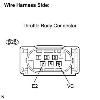
Disconnect the B28 throttle body connector.
-
Measure the voltage of the throttle body connector.
Standard voltage Tester Connection Specified Condition VC (B28-3) - E2 (B28-2) 4.5 to 5.5 V -
Reconnect the throttle body connector.
NG
REPLACE ECM
OK
-
-
REPLACE THROTTLE BODY ASSEMBLY
-
Replace the throttle body assembly Click here.
-
Perform electronic throttle learning Click here.
NEXT 
END
-