SFI SYSTEM (w/ Electronic Throttle Control System), Diagnostic DTC:P0112, P0113

| DTC Code | DTC Name |
|---|---|
| P0112 | Intake Air Temperature Circuit Low Input |
| P0113 | Intake Air Temperature Circuit High Input |
DESCRIPTION
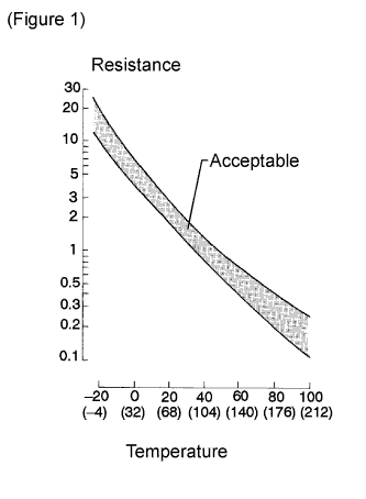
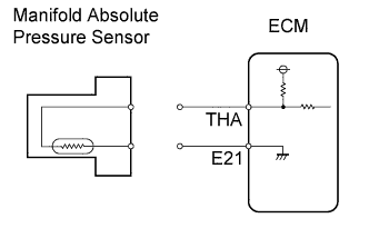
The Intake Air Temperature (IAT) sensor is built into the manifold absolute pressure sensor, and monitors the intake air temperature. The IAT sensor has a built-in thermistor that varies its resistance depending on the temperature of the intake air. When the air temperature is low, the resistance in the thermistor increases. When the temperature is high, the resistance drops. The variations in resistance are reflected in voltage applied to the ECM terminal (see figure 1).
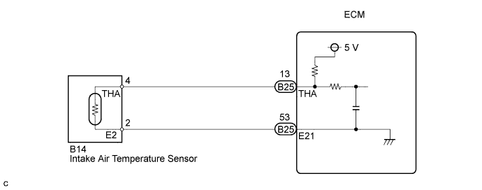
The IAT sensor is connected to the ECM. The 5 V power source voltage in the ECM is applied to the IAT sensor from terminal THA via resistor R.
Resistor R and the IAT sensor are connected in series. When the resistance value of the IAT sensor changes in accordance with changes in the intake air temperature, the voltage at terminal THA also changes. Based on this signal, the ECM increases the fuel injection volume to improve the driveability during cold engine operation.
Tech Tips
When the IAT sensor output is outside the normal range, the ECM determines this as a malfunction.
| DTC No. | DTC Detection Condition | Trouble Area |
|---|---|---|
| P0112 | IAT sensor output is less than -40°C (-40°F) for 0.5 seconds (3 trip detection logic) |
|
| P0113 | IAT sensor output is more than 140°C (284°F) for 0.5 seconds (3 trip detection logic) |
|
Tech Tips
-
DTC P0112 is detected when the engine idles for approximately 5 minutes.
-
DTC P0113 is detected when the ignition switch is ON or the engine is running.
-
When DTC P0112 or P0113 is detected, check the intake air temperature by entering following menus Powertrain / Engine and ECT / Data List / Intake Air.
| Temperature Displayed | Malfunction |
|---|---|
| Less than -40°C (-40°F) | Open circuit or short +B circuit |
| More than 140°C (284°F) | Short circuit |
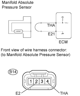
WIRING DIAGRAM
INSPECTION PROCEDURE
Note
After replacing the ECM, perform electronic throttle learning Click here.
Tech Tips
Read freeze frame data using the intelligent tester. The ECM records vehicle and driving condition information as freeze frame data the moment a DTC is stored. When troubleshooting, freeze frame data can help determine if the vehicle was moving or stationary, if the engine was warmed up or not, if the air-fuel ratio was lean or rich, and other data from the time the malfunction occurred.
PROCEDURE
-
READ VALUE USING INTELLIGENT TESTER (INTAKE AIR)
-
Connect the intelligent tester to the DLC3.
-
Turn the ignition switch to ON and turn the tester on.
-
Enter the following menus: Powertrain / Engine and ECT / Data List / Intake Air.
-
Read the value.
Result Result Proceed to Less than -40°C (-40°F) A More than 140°C (284°F) B Same as actual intake air temperature C Tech Tips
-
If there is an open circuit, the intelligent tester indicates less than -40°C (-40°F).
-
If there is a short to GND, the intelligent tester indicates more than 140°C (284°F).
-
B 
CHECK WIRE HARNESS (CHECK FOR SHORT IN WIRE HARNESS) Click here
C 
CHECK FOR INTERMITTENT PROBLEMS Click here
A 
-
-
CHECK HARNESS AND CONNECTOR (CHECK FOR OPEN IN WIRE HARNESS)
-
Confirm good condition at the manifold absolute pressure sensor.
-
Disconnect the manifold absolute pressure sensor connector.
-
Connect terminals THA and E2 of the manifold absolute pressure sensor wire harness side connector.
-
Connect the intelligent tester to the DLC3.
-
Turn the ignition switch to ON and turn the tester on.
-
Enter the following menus: Powertrain / Engine and ECT / Data List / Intake Air.
-
Read the value.
Standard 140°C (284°F) or more -
Reconnect the manifold absolute pressure sensor connector.
NG
CHECK HARNESS AND CONNECTOR (INTAKE AIR TEMPERATURE SENSOR - ECM) Click here
OK 
REPLACE MANIFOLD ABSOLUTE PRESSURE SENSOR Click here
-
-
CHECK HARNESS AND CONNECTOR (INTAKE AIR TEMPERATURE SENSOR - ECM)
-
Disconnect the manifold absolute pressure sensor connector.
-
Disconnect the ECM connector.
-
Measure the resistance according to the valve(s) in the table below.
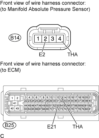
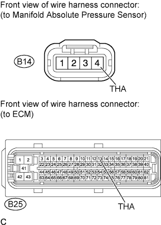
Standard Resistance Tester Connection Condition Specified Condition B14-4 (THA) - B25-13 (THA) Always Below 1 Ω B14-2 (E2) - E25-53 (E21) Always Below 1 Ω -
Reconnect the manifold absolute pressure sensor connector.
-
Reconnect the ECM connector.
NG
REPAIR OR REPLACE HARNESS AND CONNECTOR
OK
REPLACE ECM Click here
-
-
CHECK WIRE HARNESS (CHECK FOR SHORT IN WIRE HARNESS)
-
Disconnect the manifold absolute pressure sensor connector.
-
Connect the intelligent tester to the DLC3.
-
Turn the ignition switch to ON and turn the tester on.
-
Enter the following menus: Powertrain / Engine and ECT / Data List / Intake Air.
-
Read the value.
Standard Less than -40°C (-40°F) -
Reconnect the manifold absolute pressure sensor connector.
NG
CHECK HARNESS AND CONNECTOR (INTAKE AIR TEMPERATURE SENSOR - ECM) Click here
OK
REPLACE MANIFOLD ABSOLUTE PRESSURE SENSOR Click here
-
-
CHECK HARNESS AND CONNECTOR (INTAKE AIR TEMPERATURE SENSOR - ECM)
-
Disconnect the manifold absolute pressure sensor connector.
-
Disconnect the ECM connector.
-
Measure the resistance according to the valve(s) in the table below.
Standard Resistance Tester Connection Condition Specified Condition B14-4 (THA) or B25-13 (THA) - Body ground Always 10 kΩ or higher -
Reconnect the manifold absolute pressure sensor connector.
-
Reconnect the ECM connector.
NG
REPAIR OR REPLACE HARNESS AND CONNECTOR
OK
REPLACE ECM Click here
-