SFI SYSTEM (w/ Electronic Throttle Control System), Diagnostic DTC:P2100, P2111

| DTC Code | DTC Name |
|---|---|
| P2100 | Throttle Actuator Control Motor Circuit / Open |
| P2111 | Throttle Actuator Control System - Stuck Open |
DESCRIPTION
The throttle actuator is operated by the ECM, and opens and closes the throttle valve using gears. The opening angle of the throttle valve is detected by the Throttle Position (TP) sensor, which is mounted on the throttle body. The TP sensor provides feedback to the ECM in order that it can control the throttle actuator, and therefore the throttle valve appropriately in response to driver inputs.
Tech Tips
This ETCS (Electronic Throttle Control System) does not use a throttle cable.
| DTC No. | DTC Detection Condition | Trouble Area |
|---|---|---|
| P2100 | The driving IC detects a malfunction during throttle operation. (1 trip detection logic) |
|
| P2111 |
Either of following condition is met: (1 trip detection logic) |
|
Tech Tips
Detection is always performed for P2100 and P2111 when the ignition switch in the ON position or the engine is running.
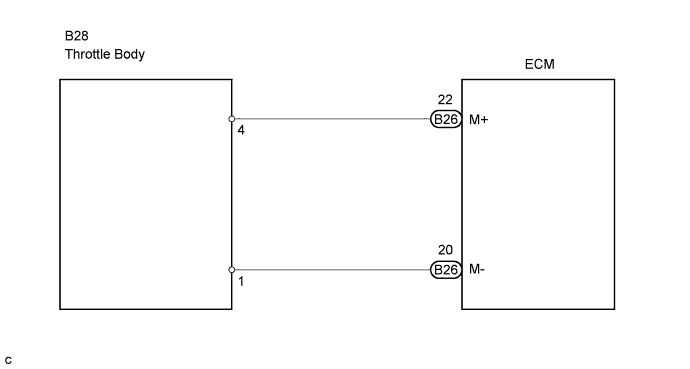
WIRING DIAGRAM
INSPECTION PROCEDURE
Note
After cleaning the throttle body, perform electronic throttle learning Click here.
Tech Tips
Read freeze frame data using the intelligent tester. The ECM records vehicle and driving condition information as freeze frame data the moment a DTC is stored. When troubleshooting, freeze frame data can help determine if the vehicle was moving or stationary, if the engine was warmed up or not, if the air-fuel ratio was lean or rich, and other data, from the time the malfunction occurred.
PROCEDURE
-
CHECK HARNESS AND CONNECTOR (THROTTLE BODY - ECM)
-
Disconnect the B28 throttle body connector.
-
Disconnect the B25 and B26 ECM connectors
-
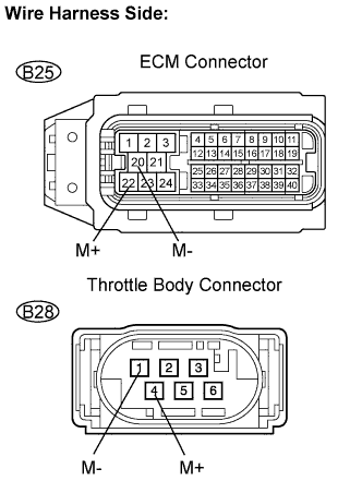
Measure the resistance between the throttle body connector and ECM connector.
Standard resistance (Check for open) Tester Connection Specified Condition M+ (B28-4) - M+ (B26-22) Below 1 Ω M- (B28-1) - M- (B26-20) Below 1 Ω Standard resistance (Check for short) Tester Connection Specified Condition M+ (B28-4) or M+ (B26-22) - Body ground 10 kΩ or higher M- (B28-1) or M- (B26-20) - Body ground 10 kΩ or higher -
Reconnect the throttle body connector.
-
Reconnect the ECM connector.
NG 
REPAIR OR REPLACE HARNESS AND CONNECTOR
OK 
-
-
CHECK THROTTLE BODY ASSEMBLY (VISUALLY CHECK THROTTLE VALVE)
-
Check for contamination between the throttle valve and the housing and throttle valve moves smoothly.
NG
CLEAN THROTTLE BODY ASSEMBLY
OK
-
-
REPLACE THROTTLE BODY ASSEMBLY
-
Replace the throttle body assembly Click here.
-
Perform electronic throttle learning Click here.
NEXT
-
-
READ VALUE OF THROTTLE POSITION SENSOR
-
Connect the intelligent tester to DLC3.
-
Turn the ignition switch ON.
-
Turn the tester ON.
-
Enter the following menus: Power train / Engine / Data List / Throttle POS.
-
Read the throttle position sensor value when the accelerator pedal is depressed.
OK The throttle position sensor value varies with a change in the angle of the accelerator pedal.
NG
CHECK HARNESS AND CONNECTOR AGAIN (THROTTLE BODY - ECM)
OK 
CHECK WHETHER DTC OUTPUT RECURS
-