SFI SYSTEM (w/ Electronic Throttle Control System), Diagnostic DTC:P0571

| DTC Code | DTC Name |
|---|---|
| P0571 | Brake Switch "A" Circuit |
DESCRIPTION
The stop light switch has a duplex system (signals STP and ST1-) to memorize the abnormality when the signals of depressing and releasing the brake pedal are detected simultaneously.
Tech Tips
Normal condition is as shown in the table.
| Signal | Brake pedal released | In transition | Brake pedal depressed |
|---|---|---|---|
| STP | OFF | ON | ON |
| ST1- | ON | ON | OFF |
| DTC No. | DTC Detection Condition | Trouble Area |
|---|---|---|
| P0571 | All of the following conditions are met: (1 trip detection logic)
|
|
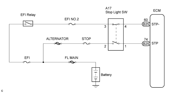
WIRING DIAGRAM
INSPECTION PROCEDURE
Note
After replace the ECM, perform electronic throttle learning Click here.
PROCEDURE
-
CHECK STOP LIGHT OPERATION
-
Check if the stop lights come on and go off normally when the brake pedal is depressed and released.
OK The stop lights come ON when you depress the brake pedal.
NG 
REPAIR OR REPLACE STOP LIGHT SWITCH CIRCUIT
OK 
-
-
INSPECT STOP LIGHT SWITCH ASSEMBLY
-
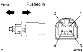
Measure the resistance between each pair of the terminals.
Standard resistance Switch Position Tester Connection Specified Condition Switch pin free 1 - 2 Below 1 Ω Switch pin free 3 - 4 10 kΩ or higher Switch pin pushed in 1 - 2 10 kΩ or higher Switch pin pushed in 3 - 4 Below 1 Ω
NG
REPLACE STOP LIGHT SWITCH ASSEMBLY
OK
-
-
CHECK STP AND ST1- SIGNAL
-
Connect the intelligent tester II to the DLC3.
-
Turn the engine switch ON (IG) and turn the intelligent tester II ON.
-
Select the following menu items: Powertrain / Engine and ECT / Data List / Stop Light SW.
-
Check the result.
Standard Brake Pedal Specified Condition Depressed STP Signal ON Released STP Signal OFF -
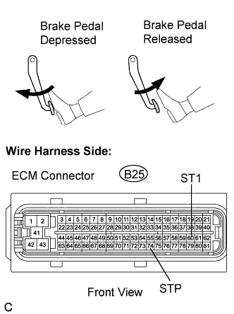
Measure the voltage between the specified terminals of the B25 ECM connectors and body ground.
Standard voltage Tester Connection Brake Pedal Specified Condition ST1 - (B25-60) - Body ground Depressed Below 1.5 V ST1 - (B25-60) - Body ground Released 7.5 to 14 V
OK
GO TO "CHECK FOR INTERMITTENT PROBLEMS"
NG
-
-
CHECK HARNESS AND CONNECTOR (STOP LIGHT SWITCH - ECM)
-
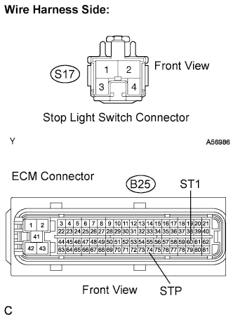
Disconnect the S17 stop light switch connector.
-
Disconnect the B25 ECM connector.
-
Check the resistance.
Standard resistance (Check for open) Tester Connection Specified Condition Stop light switch (S17-1) - STP (B25-74) Below 1 Ω Stop light switch (S17-4) - ST1- (B25-66) Below 1 Ω -
Reconnect the stop light switch connector.
-
Reconnect the ECM connector.
NG
REPAIR OR REPLACE HARNESS AND CONNECTOR
OK 
REPLACE ECM
-