SFI SYSTEM (w/ Electronic Throttle Control System) TERMINALS OF ECM

Tech Tips
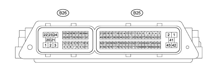
The standard normal voltage between each pair of the ECM terminals is shown in the table below. The appropriate conditions for checking each pair of the terminals are also indicated. The result of checks should be compared with the standard normal voltage for that pair of the terminals, displayed in the Specified Condition column. The illustration above can be used as a reference to identify the ECM terminal locations.
| Terminal No. (Symbol) | Wiring Color | Terminal Description | Condition | Specified Condition |
|---|---|---|---|---|
| B26-22 (BATT) - B26-1 (E1) | LG - W-B | Battery (for measuring battery voltage and for ECM memory) | Always | 11 to 14 V |
| B26-4 (IGSW) - B26-1 (E1) | R - W-B | Ignition switch | Ignition switch ON | 11 to 14 V |
| B26-24 (+B) - B26-1 (E1) | P - W-B | Power source of ECM | Ignition switch ON | 11 to 14 V |
| B26-23 (+B1) - B26-1 (E1) | Y - W-B | Power source of ECM | Ignition switch ON | 11 to 14 V |
| B26-35 (MREL) - B26-1 (E1) | GR - W-B | EFI main relay | Ignition switch ON | Below 1.5 V |
| B25-57 (VC) - B25-35 (ETA) | Y - BR*1, P*2 | Power source of throttle position sensor (specific voltage) | Ignition switch ON | 4.5 to 5.5 V |
| B26-11 (VCPA) - B26-10 (EPA) | B - LG | Power source of accelerator pedal position sensor (for VPA) | Ignition switch ON | 4.5 to 5.5 V |
| B26-19 (VCP2) - B26-18(EPA2) | W - BR*1, V*2 | Power source of accelerator pedal position sensor (for VPA2) | Ignition switch ON | 4.5 to 5.5 V |
| B25-56 (VC2) - B25-53 (E21) | R - BR | Power source of manifold absolute pressure sensor (specific voltage) | Ignition switch ON | 4.5 to 5.5 V |
| B25-80 (VCG1) - B26-1 (E1) | BE or O - W-B | Power source of camshaft position sensor (specific voltage) | Ignition switch ON | 4.5 to 5.5 V |
| B25-52 (PIM) - B25-53 (E21) | Y - BR | Manifold absolute pressure sensor | Idling | 1.2 to 2.0 V |
| B25-14 (VTA1) - B25-35 (ETA) | GR - BR*1, P*2 | Throttle position sensor 1 (for engine control) |
Ignition switch ON, Accelerator pedal fully released | 0.2 to 1.0 V |
| Ignition switch ON, Accelerator pedal fully depressed | 4.2 to 4.8 V | |||
| B25-15 (VTA2) - B25-35 (ETA) | R - BR *1, P *2 | Throttle position sensor 2 (for engine control) |
Ignition switch ON, Accelerator pedal fully released with warm engine | 4.0 to 4.8 V |
| Ignition switch ON, Accelerator pedal fully depressed | 0.2 to 1.0 V | |||
| B26-9 (VPA) - B26-10 (EPA) | R - LG | Accelerator pedal position sensor 1 (for engine control) |
Ignition switch ON, Accelerator pedal fully released | 0.7 to 1.2 V |
| Ignition switch ON, Accelerator pedal fully depressed | 2.8 to 4.6 V | |||
| B26-17 (VPA2) - B26-18 (EPA2) | L - BR*1, V*2 | Accelerator pedal position sensor 2 (for engine control) |
Ignition switch ON, Accelerator pedal fully released | 1.2 to 2.0 V |
| Ignition switch ON, Accelerator pedal fully depressed | 3.6 to 4.6 V | |||
| B25-13 (THA) - B25-53 (E21) | W -BR | Intake air temperature sensor | Idling, Intake air temperature 20°C (68°F) | 1.5 to 3.0 V |
| B25-12 (THW) - B25-30 (E2) | R - BR | Engine coolant temperature sensor | Idling, Engine coolant temperature 80°C (176°F) | 0.2 to 1.0 V |
| B25-47 (#1) - B26-21 (E01) B25-48 (#2) - B26-21 (E01) B25-67 (#3) - B26-21 (E01) |
W - W-B B - W-B R - W-B |
Injector | Ignition switch ON | 11 to 14 V |
| B25-39 (IGT1) - B26-1 (E1) B25-40 (IGT2) - B26-1 (E1) B25-21 (IGT3) - B26-1 (E1) |
G - W-B B - W-B BE or O - W-B |
Ignition coil with igniter (ignition signal) | Idling | Pulse generation (See waveform 1) |
| B25-59 (G1) - B25-60 (G-) | P - W-B | Camshaft position sensor | Idle after engine warmed-up | Pulse generation (See waveform 2) |
| B25-6 (NE+) - B25-5 (NE-) | P - L | Crankshaft position sensor | Idle after engine warmed-up | Pulse generation (See waveform 2) |
| B26-40 (STA) - B26-1 (E1) | L*1, GR*3 - W-B | Starter signal | Cranking | 5.5 V or more |
| B26-26 (FC) - B26-1 (E1) | G - W-B | Fuel pump control | Ignition switch ON | 11 to 14 V |
| B25-34 (OX1A) - B25-32 (E11) | W - B | Heated oxygen sensor (Sensor 1) | Maintain engine speed at 2500 rpm for 2 minutes after warming up sensor | Pulse generation (See waveform 3) |
| B25-36 (OX1B) - B25-37 (E12) | Y - BR | Heated oxygen sensor (Sensor 2) | Maintain engine speed at 2500 rpm for 2 minutes after warming up sensor | Pulse generation (See waveform 4) |
| B25-2 (HT1A) - B26-1 (E1) | L - W-B | Heated oxygen sensor heater | Ignition switch ON | 11 to 14 V |
| B25-41 (HT1B) - B26-1 (E1) | R - W-B | Heated oxygen sensor heater | Ignition switch ON | 11 to 14 V |
| B25-17 (KNK1) - B25-18 (KNK2) | G - R | Knock sensor | Maintain engine speed at 4000 rpm after warming up engine | Pulse generation (See waveform 5) |
| B25-42 (OCV-) - B26-1 (E1) | G - W-B | Camshaft timing oil control valve | Idling | Pulse generation (See waveform 6) |
| B25-22 (EVP1) - B26-1 (E1) | V - W-B | EVAP VSV | Ignition switch ON | 11 to 14 V |
| B26-31 (STP) - B26-1 (E1) | G - W-B | Stop light switch | Brake pedal depressed | 11 to 14 V |
| Brake pedal released | Below 1.5 V | |||
| B26-7 (ST1-) - B26-1 (E1) | Y - W-B | Stop light switch | Brake pedal depressed | Below 1.5 V |
| Brake pedal released | 11 to 14 V | |||
| B26-5 (W) - B26-1 (E1) | BE or O - W-B | MIL | Ignition switch ON (MIL goes on) |
Below 3.0 V |
| B26-38 (SPD) - B26-1 (E1) | Y - W-B | Speed signal from skid control ECU | Ignition switch ON, Rotate driving wheel slowly | Pulse generation |
| B26-2 (M+) - B26-3 (M-) | B - W | Throttle actuator | Idling with warm engine | Pulse generation (See waveform 7) |
| B26-13 (TACH) - B26-1 (E1) | P - W-B | Engine speed signal | Idling | Pulse generation (See waveform 8) |
| B25-61 (SIL) - B26-1 (E1) | GR - W-B | Terminal SIL of DLC3 | Connect intelligent tester to DLC3 | Pulse generation |
| B26-30 (TC) - B26-1 (E1) | P - W-B | Mode signal switch | Ignition switch ON | 9 to 14 V |
| B26-8 (ELS) - B26-1 (E1) | B - W-B | Taillight switch | Taillight ON | 11 to 14 V |
| B26-28 (CAN+) - B26-36 (CAN-) | B - W | CAN communication | Ignition switch ON | Pulse generation (See waveform 9) |
| B25-8 (D) - B26-1 (E1) | P - W-B | Clutch switch | Ignition switch ON, Clutch pedal depressed | Below 1.5 V |
| Ignition switch ON, Clutch pedal released | 11 to 14 V |
*1 : w/ MMT
*2 : w/ VSC
*3 : for Manual transaxle models
-
WAVEFORM 1
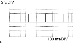
Igniter IGT Signal (from ECM to Igniter) ECM Terminal Name Between IGT1 (to IGT3) and E1 Tester Range 2 v/DIV, 100 ms/DIV Condition Idling Tech Tips
The wavelength becomes shorter as engine rpm increases.
-
WAVEFORM 2
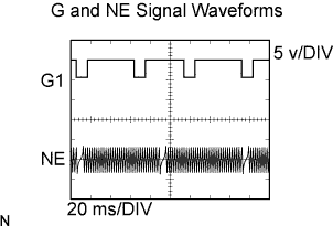
Camshaft Position Sensor, Crankshaft Position Sensor ECM Terminal Name (a) Between G1 and G-
(b) Between NE+ and NE-
Tester Range 5 v/DIV, 20 ms/DIV Condition Idle after engine warmed-up Tech Tips
-
The wavelength becomes shorter as engine rpm increases.
-
-
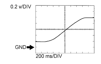
WAVEFORM 3
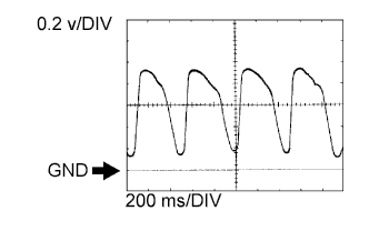
Heated Oxygen Sensor (Sensor 1) ECM Terminal Name Between OX1A and E11 Tester Range 0.2 v/DIV, 200 ms/DIV Condition Maintain engine RPM at 2500 rpm after engine warmed-up Tech Tips
In the Data List, the items O2S B1 S1 show the ECM input values of the HO2S (sensor 1).
-
WAVEFORM 4
Heated Oxygen Sensor (Sensor 2) ECM Terminal Name Between OX1B and E12 Tester Range 0.2 v/DIV, 200 ms/DIV Condition Maintain engine rpm at 2500 rpm after engine warmed-up Tech Tips
In the Data List, the items O2S B1 S2 show the ECM input values of the HO2S (sensor 2).
-
WAVEFORM 5
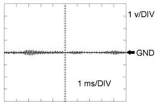
Knock Sensor ECM Terminal Name Between KNK1 and KNK2 Tester Range 1 v/DIV, 1 ms/DIV Condition Maintain engine rpm at 4000 rpm after engine warmed-up Tech Tips
-
The wavelength becomes shorter as engine rpm increases.
-
The waveforms and amplitudes displayed differ slightly depending on the vehicle.
-
-
WAVEFORM 6
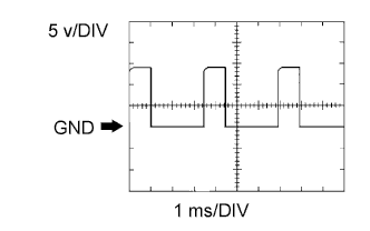
VVT OCV ECM Terminal Name Between OCV- and E1 Tester Range 5 v/DIV, 1 ms/DIV Condition Idling -
WAVEFORM 7
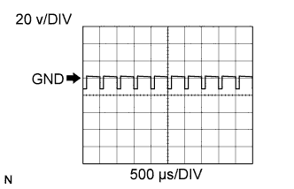
Throttle Actuator Positive Terminal ECM Terminal Name Between M+ and M- Tester Range 20 v/DIV, 500 μs/DIV Condition Idling with warm engine Tech Tips
The duty ratio varies depending on the throttle actuator operation.
-
WAVEFORM 8
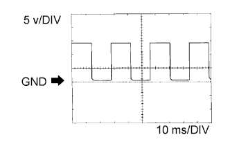
Engine Revolution Signal ECM Terminal Name Between TACH and E1 Tester Range 5 v/DIV, 10 ms/DIV Condition Idling with warm engine Tech Tips
The wavelength becomes shorter as the engine rpm increases.
-
WAVEFORM 9
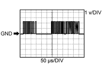
CAN Communication Signal (Reference) ECM Terminal Name Between CAN+ and CAN- Tester Range 1 v/DIV, 50 μs/DIV Condition Ignition switch ON Tech Tips
The waveform varies depending on the CAN communication signal.