МЕХАНИЧЕСКАЯ ТРАНСМИССИЯ В СБОРЕ УСТАНОВКА
-
INSTALL TRANSMISSION CONTROL CABLE BRACKET NO.1
-
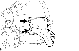
Install the transmission control cable bracket No.1 with the 2 bolts.
- Torque:
- 28 N*m { 286 kgf*cm, 21 ft.*lbf }
-
-
INSTALL REAR ENGINE MOUNTING INSULATOR ASSEMBLY
-
Install the engine mounting insulator assembly rear with the 4 bolts.
- Torque:
- 29 N*m { 296 kgf*cm, 21 ft.*lbf }
-
-
INSTALL MANUAL TRANSMISSION UNIT ASSEMBLY
-
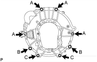
Install the transmission unit assembly with the 8 bolts.
- Torque:
- Bolt A
- 72 N*m { 729 kgf*cm, 53 ft.*lbf }
- Bolt B
- 69 N*m { 700 kgf*cm, 51 ft.*lbf }
- Bolt C
- 37 N*m { 377 kgf*cm, 27 ft.*lbf }
-
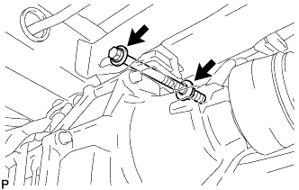
Install the transmission unit assembly with the bolt, nut and 2 washers to the frame.
- Torque:
- 98 N*m { 999 kgf*cm, 72 ft.*lbf }
Note
-
Insert the bolt from the left side of the vehicle.
-
Tighten the nut while holding the bolt.
-
-
INSTALL STARTER ASSEMBLY (for 2.2 kW Type)
-
Install the starter with the 2 bolts and nut.
- Torque:
- 69 N*m { 700 kgf*cm, 51 ft.*lbf }
-
Install the stay with the 2 bolts and nut.
- Torque:
- 69 N*m { 104 kgf*cm, 51 ft.*lbf }
-
Connect the 30 terminal with the nut.
- Torque:
- 9.8 N*m { 100 kgf*cm, 7 ft.*lbf }
-
Install the terminal cap.
-
Connect the starter connector.
-
-
INSTALL STARTER ASSEMBLY (for 2.7 kW Type)
-
Install the starter with the 2 bolts, nut and stay.
- Torque:
- 69 N*m { 700 kgf*cm, 51 ft.*lbf }
-
Install the starter stay with the 2 bolts and nut.
- Torque:
- Bolt
- 37 N*m { 380 kgf*cm, 27 ft.*lbf }
- Nut
- 12.5 N*m { 130 kgf*cm, 9 ft.*lbf }
-
Connect the 30 terminal with the nut.
- Torque:
- 21 N*m { 215 kgf*cm, 16 ft.*lbf }
-
Install the terminal cap.
-
Connect the starter connector.
-
-
INSTALL CLUTCH RELEASE CYLINDER ASSEMBLY
-
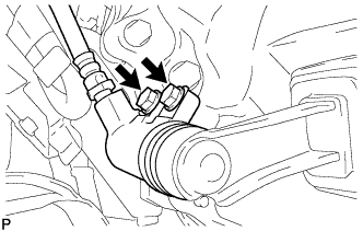
Install the clutch release cylinder with the 2 bolts.
- Torque:
- 12 N*m { 120 kgf*cm, 9 ft.*lbf }
-
-
CONNECT WIRE HARNESS
-
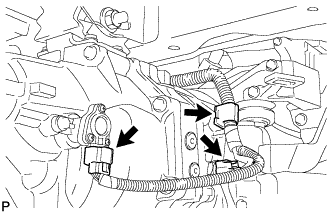
Connect the 2 connectors and clamp.
-
-
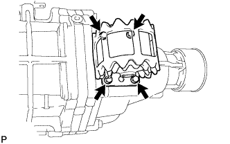
INSTALL TRANSMISSION CONTROL CABLE ASSEMBLY
-
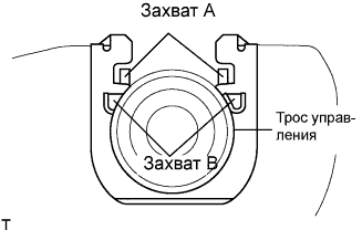
Install 2 new clips to the transmission control cable bracket No.1.
-
Install the transmission control cable assembly to the transmission control cable bracket No.1.
Note
-
Be sure that A claws of the clips are firmly engaged into the bracket grooves.
-
Be sure the cable is set in the clip with both B claws erected to prevent slippage of the cable in the opposite direction.
-
-
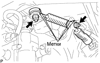
Align the matchmarks on the control cable assembly and the outer lever.
-
Install the transmission control cable assembly to the outer levers with the 2 nuts.
- Torque:
- 37 N*m { 377 kgf*cm, 27 ft.*lbf }
-
-
INSTALL PROPELLER SHAFT ASSEMBLY (for Long Wheelbase)
-
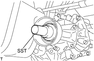
Снимите SST с удлинителя картера трансмиссии.
-
Установите карданный вал в сборе в удлинитель картера трансмиссии.
-
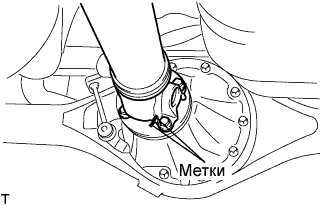
Совместите метки на фланце карданного вала и фланце дифференциала.
-
Закрепите карданный вал в сборе с помощью 4 гаек, 4 болтов и 4 шайб.
- Torque:
- 74 Н*м { 755 кгс*см, 54 фунт-сила-фута }
-
-
INSTALL PROPELLER WITH CENTER BEARING SHAFT ASSEMBLY (for Super Long Wheelbase)
-
Снимите SST с удлинителя картера трансмиссии.
-
Установите карданный вал с центральным подшипником в сборе в удлинитель картера трансмиссии.
-
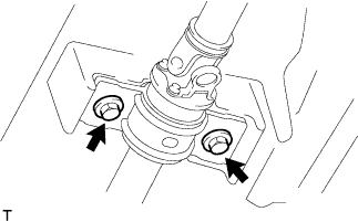
Установите центральный опорный подшипник № 1 в сборе и временно затяните 2 болта.
-
Совместите метки на фланце карданного вала и фланце дифференциала.
-
Закрепите карданный вал в сборе с помощью 4 гаек, 4 болтов и 4 шайб.
- Torque:
- 74 Н*м { 755 кгс*см, 54 фунт-сила-фута }
-
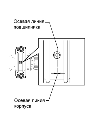
Осевая линия кронштейна должна проходить под прямым углом к осевому направлению вала.
-
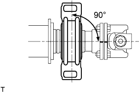
Отрегулируйте центральный опорный подшипник № 1 в сборе.
Tech Tips
-
Отрегулируйте центральный опорный подшипник № 1 для установки углов на порожнем автомобиле, как показано на рисунке.
-
В таких же условиях проверьте осевую линию в осевом направлении. При необходимости отрегулируйте положение подшипника.
-
Осевая линия центрального подшипника и осевая линия корпуса центрального подшипника должны быть отрегулированы таким образом, чтобы расстояние между ними попадало в диапазон -1,0-1,0 мм (-0,0394-0,0394 дюйма) в продольном направлении (вдоль автомобиля) в разгруженном состоянии автомобиля.
-
-
Затяните 2 болта.
- Torque:
- 36 Н*м { 369 кгс*см, 27 фунт-сила-футов }
-
-
INSTALL EXHAUST PIPE ASSEMBLY FRONT NO.2 (for Long Wheelbase)
-
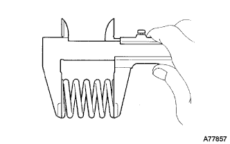
Inspect the compression spring.
-
Using vernier calipers, measure the free length of the compression springs.
Minimum length 40.5 mm (1.594 in.) Tech Tips
If the free length is less than the minimum, replace the compression spring.
-
-
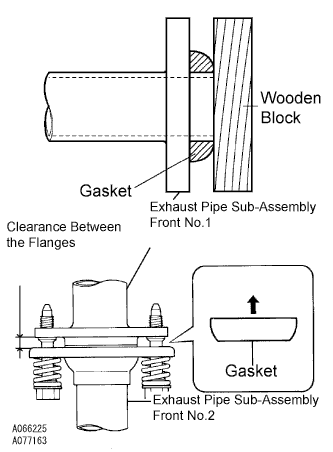
Install the gasket.
-
Fully insert a new gasket to the exhaust pipe sub-assembly front No.1 by hand.
-
Using a wooden block, uniformly strike the gasket so that the gasket and exhaust pipe sub-assembly front No.1 are properly fit.
Note
-
Be careful with the installation direction of the gasket.
-
Do not damage the outer face.
-
Do not reuse the gasket.
-
To ensure a proper seal, do not use the exhaust pipe sub-assembly front No.2 to force the gasket onto the exhaust pipe sub-assembly front No.1.
-
-
-
Connect the exhaust pipe support, and install a new gasket and the exhaust pipe sub-assembly front No.2 with the 4 bolts, 2 nuts, and 2 compression springs.
- Torque:
- Exhaust pipe sub-assembly front No.1 side
- 43 N*m { 438 kgf*cm, 32 ft.*lbf }
- Exhaust pipe assembly tail side
- 48 N*m { 489 kgf*cm, 35 ft.*lbf }
Note
After installation, check that the clearance is almost same at any point between the flanges of the exhaust pipe sub-assembly front No.2 and exhaust pipe sub-assembly front No.1.
-
-
INSTALL EXHAUST PIPE ASSEMBLY FRONT NO.2 (for Super Long Wheelbase)
-
Inspect the compression spring.
-
Using vernier calipers, measure the free length of the compression springs.
Minimum length 40.5 mm (1.594 in.) Tech Tips
If the free length is less than the minimum, replace the compression spring.
-
-
Install the gasket.
-
Fully insert a new gasket to the exhaust pipe sub-assembly front No.1 by hand.
-
Using a wooden block, uniformly strike the gasket so that the gasket and exhaust pipe sub-assembly front No.1 are properly fit.
Note
-
Be careful with the installation direction of the gasket.
-
Do not damage the gasket.
-
Do not reuse the gasket.
-
To ensure a proper seal, do not use the exhaust pipe sub-assembly front No.2 to force the gasket onto the exhaust pipe sub-assembly front No.1.
-
-
-
Connect the exhaust pipe support, and install a new gasket and the exhaust pipe sub-assembly front No.2 with the 4 bolts, 2 nuts, and 2 compression springs.
- Torque:
- Exhaust pipe sub-assembly front No.1 side
- 43 N*m { 438 kgf*cm, 32 ft.*lbf }
- Exhaust pipe assembly center side
- 48 N*m { 489 kgf*cm, 35 ft.*lbf }
Note
After installation, check that the clearance is almost same at any point between the flanges of the exhaust pipe sub-assembly front No.2 and exhaust pipe sub-assembly front No.1 .
-
-
ADD MANUAL TRANSMISSION OIL
-
Установить автомобиль на ровной горизонтальной площадке.
-
Снимите пробку наливной горловины трансмиссии и прокладку.
-
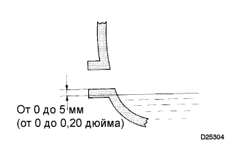
Убедитесь в том, что поверхность масла попадает в зону 5 мм (0,20 дюйма) у нижнего края наливного отверстия трансмиссии.
Класс масла по степени вязкости GL-4 Вязкость SAE 75W-90 Объем 2,2 л (2,3 кварты США, 1,9 английской кварты) Note
-
Если уровень масла слишком низкий или чрезмерно высокий, работа системы может быть нарушена.
-
После замены масла совершите пробную поездку на автомобиле, а затем снова проверьте уровень масла.
-
-
Если уровень масла низкий, проверьте, нет ли утечек.
-
Установите на место пробку наливной горловины трансмиссии и новую прокладку.
- Torque:
- 37 Н*м { 377 кгс*см, 27 фунт-сила-футов }
-
-
CONNECT CABLE TO NEGATIVE BATTERY TERMINAL
-
CHECK FOR EXHAUST GAS LEAKS
-
PERFORM INITIALIZATION
Some systems need initialization after reconnecting the cable to the negative battery terminal Click here.