МЕХАНИЧЕСКАЯ ТРАНСМИССИЯ В СБОРЕ СНЯТИЕ

-
DISCONNECT CABLE FROM NEGATIVE BATTERY TERMINAL
-
DRAIN MANUAL TRANSMISSION OIL
-
Remove the filler plug and gasket.
-
Remove the drain plug and gasket, and drain the oil.
-
Install the drain plug with a new gasket.
- Torque:
- 37 N*m { 377 kgf*cm, 27 ft.*lbf }
-
-
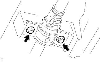
REMOVE EXHAUST PIPE ASSEMBLY FRONT NO.2 (for Long Wheelbase)
-
Remove the 4 bolts, 2 compression springs.
-
Disconnect the exhaust pipe support, and remove the exhaust pipe assembly front No.2 and 2 gaskets.
-
-
REMOVE EXHAUST PIPE ASSEMBLY FRONT NO.2 (for Super Long Wheelbase)
-
Remove the 4 bolts, 2 nuts, 2 compression springs.
-
Disconnect the exhaust pipe support, and remove the exhaust pipe assembly front No.2 and 2 gaskets.
-
-
REMOVE PROPELLER SHAFT ASSEMBLY (for Long Wheelbase)
-
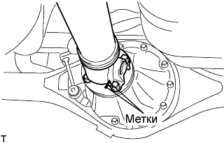
Нанесите метки на оба фланца.
-
Снимите 4 гайки с болтами и шайбами.
Tech Tips
Если фланцевое соединение разделяется с трудом, временно затяните только одну гайку и, равномерно распределяя удары, с помощью молотки и латунного стержня, отделите карданный вал от соединительного фланца дифференциала.
-
Снимите карданный вал в сборе.
-
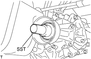
Установите SST в трансмиссию для предотвращения утечки масла.
Note
Будьте осторожны, чтобы не повредить сальник.
-
При работе с автоматической трансмиссией используйте следующий SST
- SST
- 09325-40010
-
При работе с механической трансмиссией используйте следующий SST
- SST
- 09325-20010
-
-
-
REMOVE PROPELLER WITH CENTER BEARING SHAFT ASSEMBLY (for Super Long Wheelbase)
-
Нанесите метки на оба фланца.
-
Снимите 4 гайки с болтами и шайбами.
Tech Tips
Если фланцевое соединение разделяется с трудом, временно затяните только одну гайку и, равномерно распределяя удары, с помощью молотка и латунного стержня отделите карданный вал с центральным подшипником в сборе от соединительного фланца дифференциала.
-
Выверните 2 болта и снимите центральный опорный подшипник № 1 в сборе.
-
Снимите карданный вал с центральным подшипником в сборе.
-
Установите SST в трансмиссию для предотвращения утечки масла.
Note
Будьте осторожны, чтобы не повредить сальник.
-
При работе с автоматической трансмиссией используйте следующий SST.
- SST
- 09325-40010
-
При работе с механической трансмиссией используйте следующий SST.
- SST
- 09325-20010
-
-
-
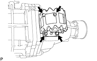
SEPARATE TRANSMISSION CONTROL CABLE ASSEMBLY
-
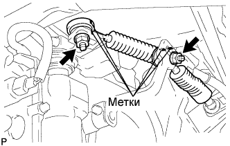
Put matchmarks on the control cable assembly and the outer lever.
-
Remove the 2 nuts and separate the transmission control cable from the outer lever.
-
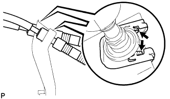
Using a screwdriver, disengage the claws of the 2 clips.
-
Remove the transmission control cable and 2 clips from the transmission control cable bracket No.1.
-
-
DISCONNECT WIRE HARNESS
-
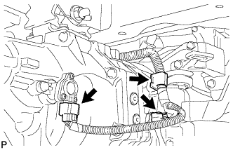
Disconnect the 2 connectors and clamp.
-
-
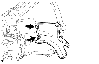
SEPARATE CLUTCH RELEASE CYLINDER ASSEMBLY
-
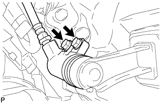
Remove the 2 bolts and separate the clutch release cylinder.
-
-
REMOVE STARTER ASSEMBLY (for 2.2 kW Type)
-
Disconnect the starter connector.
-
Remove the terminal cap.
-
Remove the nut, and disconnect the 30 terminal.
-
Remove the nut, 2 bolts, and stay.
-
Remove the nut 2 bolts, and starter assembly.
-
-
REMOVE STARTER ASSEMBLY (for 2.7 kW Type)
-
Disconnect the starter connector.
-
Remove the terminal cap.
-
Remove the nut, and disconnect the 30 terminal.
-
Remove the nut and, 2 bolts, stay and starter assembly.
-
-
REMOVE MANUAL TRANSMISSION UNIT ASSEMBLY
-
Support the manual transmission unit with a transmission jack.
-
Remove the bolt, nut, and 2 washers, and separate the transmission unit from the frame.
-
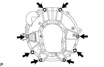
Remove the 8 bolts and manual transmission unit.
-
-
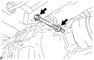
REMOVE REAR ENGINE MOUNTING INSULATOR ASSEMBLY
-
Remove the 4 bolts and rear engine mounting insulator assembly.
-
-
REMOVE TRANSMISSION CONTROL CABLE BRACKET NO.1
-
Remove the 2 bolts and transmission control cable bracket No.1.
-