МУФТА ПРЯМОЙ ПОВЫШАЮЩЕЙ ПЕРЕДАЧИ РАЗБОРКА

-
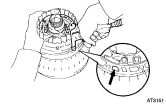
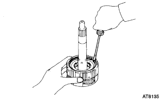
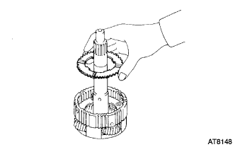
INSPECT OVERDRIVE 1 WAY CLUTCH
-
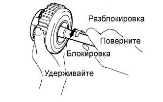
Hold the O/D direct clutch drum, and turn the input shaft. Check that the input shaft can be turned freely clockwise and locked counterclockwise.
-
-
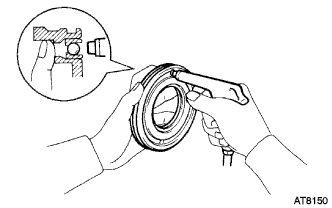
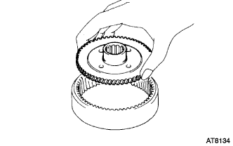
REMOVE OVERDRIVE DIRECT CLUTCH DRUM SUB-ASSEMBLY
-
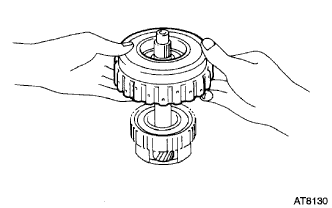
Remove the overdrive direct clutch.
-
-
INSPECT OVERDRIVE DIRECT CLUTCH DRUM SUB-ASSEMBLY
-
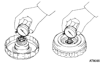
Using a dial indicator, measure the inside diameter of the clutch drum bushings.
Maximum inside diameter 27.11 mm (1.0673 in.) If the inside diameter is greater than the maximum, replace the clutch drum.
-
-
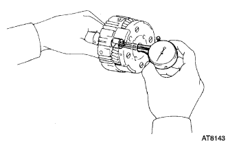
INSPECT PISTON STROKE OF OVERDRIVE DIRECT CLUTCH
-
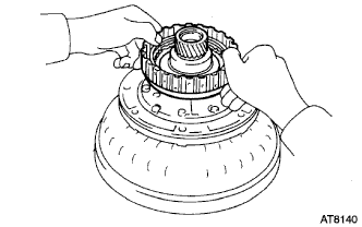
Place the oil pump onto the torque converter clutch, and then place the O/D direct clutch assembly onto the oil pump.
-
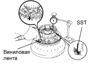
Using SST and a dial indicator, measure the O/D direct clutch piston stroke while applying and releasing compressed air (392 kPa, 4.0 kgf/cm2, 57 psi).
- SST
- 09350-30020 ( 09350-06120 )
Piston stroke 1.85 to 2.15 mm (0.0728 to 0.0846 in.) If the piston stroke is less than the limit, parts may have been assembled incorrectly, so check and reassemble again. If the piston stroke is outside the standard, select another flange.
Tech Tips
There are 8 different thicknesses for the flange.
Flange thickness: No. Thickness No. Thickness 08 3.8 mm (0.150 in.) 04 3.4 mm (0.134 in.) 07 3.7 mm (0.146 in.) 03 3.3 mm (0.130 in.) 06 3.6 mm (0.142 in.) 02 3.2 mm (0.126 in.) 05 3.5 mm (0.138 in.) 01 3.1 mm (0.122 in.)
-
-
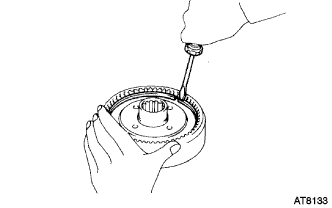
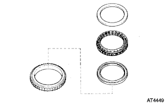
REMOVE OVERDRIVE DIRECT CLUTCH CLUTCH DISC
-
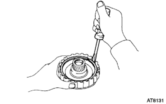
Using a screwdriver, remove the snap ring from the O/D direct clutch drum.
-
Remove the flange, the 2 plates and the 2 discs.
-
-
INSPECT OVERDRIVE DIRECT CLUTCH CLUTCH DISC
-
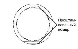
Check to see if the sliding surfaces of the disc, the plate and the flange are worn or burnt. If necessary, replace them.
Tech Tips
-
If the lining of the disc is peeled off or discolored, or even if only a part of the printed numbers is corroded, replace all discs.
-
Before assembling new discs, soak them in ATF for at least 15 minutes.
-
-
-
REMOVE OVERDRIVE CLUTCH RETURN SPRING SUB-ASSEMBLY
-
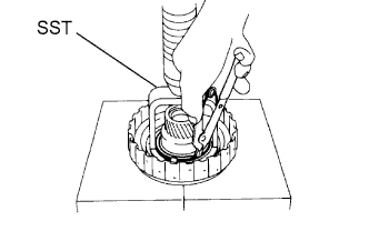
Place SST on the spring retainer, and compress the return spring with a press.
- SST
- 09350-30020 ( 09350-07040 )
Note
Stop compressing when the spring sheet is lowered to the place 1 to 2 mm (0.039 to 0.078 in.) from the snap ring groove, preventing the spring sheet from being deformed.
-
Using snap ring pliers, remove the snap ring.
-
Remove the piston return spring.
-
-
INSPECT OVERDRIVE CLUTCH RETURN SPRING SUB-ASSEMBLY
-
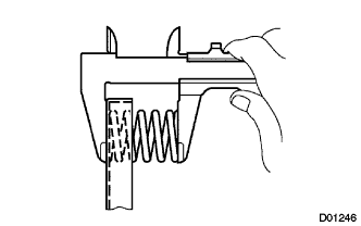
Measure the free length of the spring together with the spring seat.
Standard free length 15.8 mm (0.622 in.)
-
-
REMOVE OVERDRIVE DIRECT CLUTCH PISTON SUB-ASSEMBLY
-
Place the oil pump onto the torque converter clutch, and then place the O/D direct clutch onto the oil pump.
-
Hold the O/D direct clutch piston by hand, and apply compressed air (392 kPa, 4.0 kgf/cm2, 57 psi) to the oil pump to remove the O/D direct clutch piston.
-
Remove the O/D direct clutch piston.
Tech Tips
If the piston is at an angle and cannot be removed, press down on the protruding side and apply compressed air again, or wind vinyl tape around the piston end and remove it with needle nose pliers.
-
Remove the 2 O-rings from the piston.
-
-
INSPECT OVERDRIVE DIRECT CLUTCH PISTON SUB-ASSEMBLY
-
Check that the check ball is free by shaking the piston.
-
Check that the valve does not have leaks by applying low-pressure compressed air.
-
-
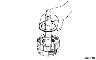
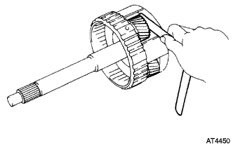
REMOVE OVERDRIVE PLANETARY RING GEAR FLANGE
-
Using a screwdriver, remove the snap ring.
-
Remove the ring gear flange.
-
-
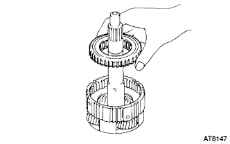
REMOVE OVERDRIVE RETAINING PLATE
-
Using a screwdriver, remove the snap ring.
-
Remove the retaining plate.
-
-
REMOVE OVERDRIVE 1 WAY CLUTCH
-
Remove the overdrive 1 way clutch outer race.
-
-
REMOVE OVERDRIVE 1 WAY CLUTCH
-
Remove the O/D one-way clutch with the retainer from the outer race.
-
Remove the 2 retainers from the one-way clutch.
-
-
REMOVE OVERDRIVE PLANETARY GEAR THRUST WASHER NO.3
-
Remove the over drive planetary gear thrust washer.
-
-
INSPECT OVERDRIVE PLANETARY GEAR ASSEMBLY
-
Using a dial indicator, measure the inside diameter of the planetary gear bushing.
Maximum inside diameter 11.27 mm (0.4437 in.) If the inside diameter is greater than the maximum, replace the planetary gear.
-
Using a feeler gauge, measure the planetary pinion gear thrust clearance.
Standard clearance 0.20 to 0.60 mm (0.0079 to 0.0236 in.) Maximum clearance 0.65 mm (0.0256 in.)
-