ТРОС МЕХАНИЗМА ПЕРЕКЛЮЧЕНИЯ ПЕРЕДАЧ УСТАНОВКА

Note
-
Use the same procedure for RHD vehicles and LHD vehicles.
-
The procedure listed below is for LHD vehicles.
-
CONNECT TRANSMISSION CONTROL CABLE ASSEMBLY
-
Rolled up the floor carpet of the front seat LH and connect the transmission control cable assembly with the 2 bolts.
- Torque:
- 8.0 N*m { 82 kgf*cm, 71 in.*lbf }
-
Install the transmission control cable bracket No. 3 to the body with the 2 nuts.
- Torque:
- 5.5 N*m { 56 kgf*cm, 49 in.*lbf }
-
Install the transmission control cable assembly to the transmission control cable bracket No. 3.
-
Turn the nut of the transmission control cable assembly approximately 180° counterclockwise. While holding the nut in place, securely push the stopper in all the way.
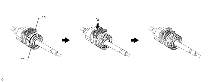
Text in Illustration *1 Stopper *2 Nut *3 Push in - - Note
Do not over-rotate the nut as it will come off the internal spring and the transmission control cable assembly will not be reusable.
-
Install the outer part of the transmission control cable assembly to the shift lock control unit assembly. Check that the spring is positioned at "A" and push in the stopper.
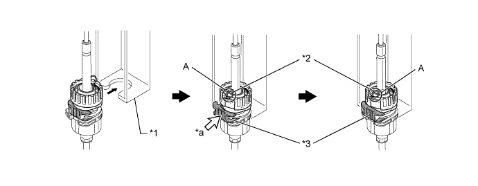
Text in Illustration *1 Shift Lock Control Unit Assembly *2 Spring *3 Stopper - - *a Push in - - Note
Ensure that the groove on the transmission control cable assembly is securely fitted to the shift lock control unit assembly.
Tech Tips
If the stopper cannot be pushed in, slightly turn the nut clockwise and then push in the stopper again.
-
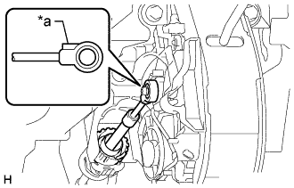
Text in Illustration *a Protrusion Connect the end of the transmission control cable assembly to the shift lock control unit assembly.
Note
-
Securely connect the cable end until if fits securely against the base of the pin.
-
Connect the cable end with the protrusion facing the front of the vehicle.
-
-
-
INSTALL INSTRUMENT PANEL FINISH PANEL LOWER CENTER
-
Введите в зацепление 8 захватов, чтобы установить нижнюю центральную отделочную накладку панели приборов.
-
-
INSTALL PARKING BRAKE HOLE COVER
-
Введите в зацепление 6 захватов, чтобы установить крышку отверстия стояночного тормоза.
-
-
INSTALL INSTRUMENT PANEL FINISH PANEL LOWER
-
Подсоедините трос устройства блокировки топливной крышки и трос управления замком капота к нижней отделочной накладке панели приборов.
-
Установите нижнюю отделочную накладку панели приборов и закрепите ее 4 фиксаторами.
-
Установите 2 фиксатора.
-
-
INSTALL INSTRUMENT PANEL UNDER COVER SUB-ASSEMBLY NO. 1
-
Введите в зацепление 3 захвата, чтобы установить нижнюю крышку панели приборов № 1.
-
Установите 2 фиксатора.
-
-
INSTALL FLOOR SHIFT POSITION INDICATOR HOUSING SUB-ASSEMBLY
-
Attach the 8 claws to install the floor shift position indicator housing sub-assembly.
-
-
INSTALL SHIFT LEVER KNOB
-
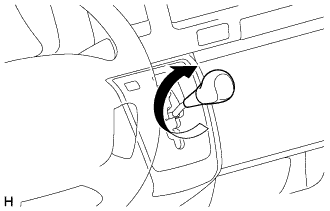
Install the shift lever knob and twist it in the direction indicated by the arrow.
-
-
INSTALL TRANSMISSION CONTROL CABLE ASSEMBLY
-
Install the transmission control cable bracket No. 2 to the under body with the 2 nuts.
- Torque:
- 5.5 N*m { 56 kgf*cm, 49 in.*lbf }
-
Connect the transmission control cable assembly to the transmission control cable bracket No. 2.
-
Install the transmission control cable assembly with the 2 bolts.
- Torque:
- 14 N*m { 143 kgf*cm, 10 ft.*lbf }
-
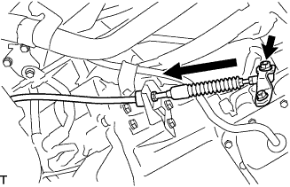
Connect the transmission control cable assembly to the control shaft lever and transmission control cable bracket No. 1 with a clip and the nut.
- Torque:
- 15 N*m { 148 kgf*cm, 11 ft.*lbf }
-
-
ADJUST SHIFT LEVER POSITION
-
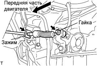
Снимите фиксатор, отверните гайку и отсоедините трос механизма переключения передач в сборе от рычага приводного вала и кронштейна троса механизма переключения передач № 1.
-
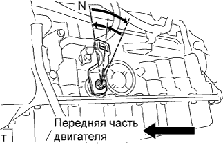
Поверните рычаг приводного вала до упора по часовой стрелке, а затем верните его на 2 метки в обратном направлении в положение N.
-
Установите рычаг переключения передач в положение N, слегка нажимая на него в направлении положения R, и установите его.
- Torque:
- 15 Н*м { 150 кгс*см, 11 фунт-сила-футов }
Note
Затяните гайку, чтобы исключить смешение деталей.
-
Проверьте режим работы и правильность работы.
-
-
INSPECT SHIFT LEVER POSITION
-
Переключая передачу только из положения P при включенном зажигании, нажмите педаль тормоза.
-
Убедитесь, что рычаг переключения передач движется плавно и перемещается под умеренным усилием.
-
Запустив двигатель, убедитесь, что при переключении рычага из положения N в положение D автомобиль двигается вперед, а при переключении в положение R - назад.
-
-
INSTALL NO. 1 ENGINE UNDER COVER
-
Install the No. 1 engine under cover with the 4 bolts.
- Torque:
- 13 N*m { 133 kgf*cm, 10 ft.*lbf }
-