СИСТЕМА АВТОМАТИЧЕСКОЙ ТРАНСМИССИИ С ЭЛЕКТРОННЫМ УПРАВЛЕНИЕМ, Diagnostic DTC:P2769/64, P2770/64
| DTC Code | DTC Name |
|---|---|
| P2769/64 | Short in Torque Converter Clutch Solenoid Circuit (Shift Solenoid Valve SL) |
| P2770/64 | Open in Torque Converter Clutch Solenoid Circuit (Shift Solenoid Valve SL) |
DESCRIPTION
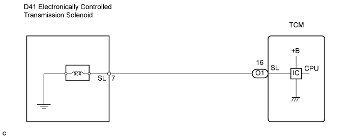
The shift solenoid valve SL is turned "ON" and "OFF" by signals from the TCM in order to control the hydraulic pressure operation, the lock-up relay valve, which then the controls operation of the lock-up clutch.
| DTC No. | DTC Detection Condition | Trouble Area |
|---|---|---|
| P2769/64 | TCM detects short in solenoid valve SL circuit when solenoid valve SL is operated. (1KD-FTV: 2-trip detection logic) (2KD-FTV: 1-trip detection logic) |
|
| P2770/64 | TCM detects open in solenoid valve SL circuit when solenoid valve SL is not operated. (1KD-FTV: 2-trip detection logic) (2KD-FTV: 1-trip detection logic) |
|
MONITOR DESCRIPTION
Based on the signals from the throttle position sensor, mass air flow meter and the crankshaft position sensor, the TCM sends a signal to the SL Solenoid Valve to regulate the hydraulic pressure and provide smoother gearshifts. The shift-solenoid valve SL responds to commands from the TCM. The valve controls the lock-up relay valve to perform the torque-converter lock-up function. If the TCM detects an open or short circuit for shift-solenoid SL, it will illuminate the MIL.
WIRING DIAGRAM
INSPECTION PROCEDURE
PROCEDURE
-
INSPECT TRANSMISSION WIRE (SL)
-
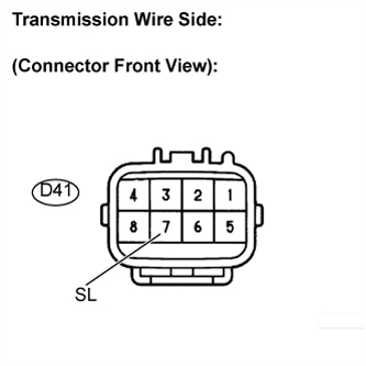
Disconnect the transmission wire connector from the transmission.
-
Measure the resistance.
Standard resistance Tester Connection Specified Condition
20°C (68°F)
7 - Body ground 11 to 15 Ω
NG 
INSPECT SHIFT SOLENOID VALVE SL Click here
OK 
-
-
CHECK HARNESS AND CONNECTOR (TRANSMISSION WIRE - TCM)
-
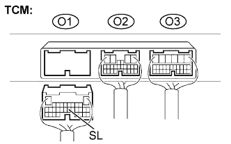
Connect the transmission wire connector to the transmission.
-
Disconnect the connector from the TCM.
-
Measure the resistance.
Standard resistance Tester Connection Specified Condition
20°C (68°F)
O1-16 (SL) - Body ground 11 to 15 Ω
NG 
REPAIR OR REPLACE HARNESS OR CONNECTOR
OK 
REPLACE TCM
-
-
INSPECT SHIFT SOLENOID VALVE SL
-
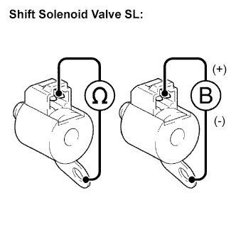
Remove the shift solenoid valve SL.
-
Measure the resistance according to the value(s) in the table below.
Standard resistance Tester Connection Specified Condition
20°C (68°F)
Solenoid Connector (SL) - Solenoid Body (SL) 11 to 15 Ω -
Connect the positive (+) lead to the terminal of the solenoid connector, and the negative (-) lead to the solenoid body.
OK The solenoid makes an operating sound.
NG
REPLACE SHIFT SOLENOID VALVE SL
OK
REPAIR OR REPLACE TRANSMISSION WIRE
-