- Click here
INSTALL SHIFT LOCK CONTROL UNIT ASSEMBLY
-
Install the shift lock control unit assembly with the 4 bolts.
14 N*m 140 kgf*cm 10 ft.*lbf -
Install the shift lock computer connector and the indicator light wire connector.
-
- Click here
CONNECT TRANSMISSION CONTROL CABLE ASSEMBLY
-
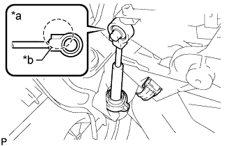
Connect the cable end to the shift lock control unit.
Table 1. Text in Illustration *a Cable End *b Protrusion Note:
-
Securely connect the cable end until if fits securely against the base of the pin.
-
Connect the cable end with the protrusion facing the front of the vehicle.
-
-
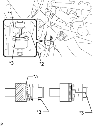
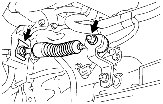
Turn the nut on the transmission control cable counterclockwise unit it stops it in place.
Table 2. Text in Illustration *1 Nut *2 Unit Housing *3 Spring *a Protrusion -
Connect the transmission control cable to the shift lock control unit housing.
Note:
-
Connect the cable outer with the protrusion on the bottom.
-
Ensure that the groove on the cable outer is securely fitted to the shift lock control unit housing.
-
Ensure that the spring is positioned as show in the illustration.
-
-
- Click here
INSTALL INSTRUMENT PANEL FINISH PANEL LOWER CENTER
-
Установите нижнюю центральную отделочную накладку панели приборов и закрепите ее 8 захватами.
-
- Click here
INSTALL PARKING BRAKE HOLE COVER
-
Установите крышку отверстия стояночного тормоза и введите в зацепление 6 захватов.
-
- Click here
INSTALL INSTRUMENT PANEL FINISH PANEL LOWER
-
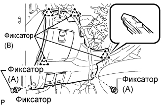
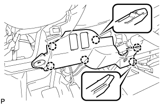
Введите в зацепление 4 фиксатора (B).
-
Установите нижнюю отделочную накладку панели приборов и закрепите ее 2 фиксаторами (A).
-
- Click here
INSTALL INSTRUMENT PANEL NO. 1 UNDER COVER SUB-ASSEMBLY
-
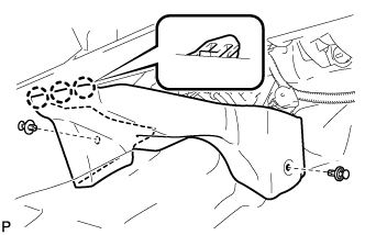
Введите в зацепление 3 захвата.
-
Установите нижнюю крышку панели приборов № 1 в сборе и закрепите ее 2 фиксаторами.
-
- Click here
INSTALL SHIFT LOCK RELEASE BUTTON
-
Install the shift lock release button to the shift position indicator housing.
-
- Click here
INSTALL SHIFT POSITION INDICATOR HOUSING SUB-ASSEMBLY
-
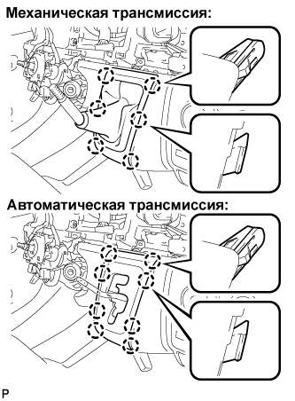
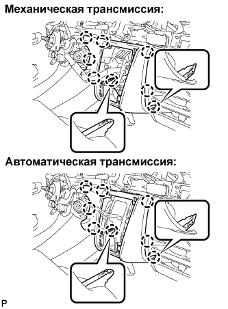
Механическая трансмиссия:
Установите чехол лючка рычага переключения передач в сборе и введите в зацепление 6 захватов.
-
Автоматическая трансмиссия:
Установите чехол лючка рычага переключения передач в сборе и введите в зацепление 8 захватов.
-
- Click here
INSTALL SHIFT LEVER KNOB
- Click here
CONNECT BATTERY NEGATIVE TERMINAL
- Click here
ADJUST SHIFT LEVER POSITION
-
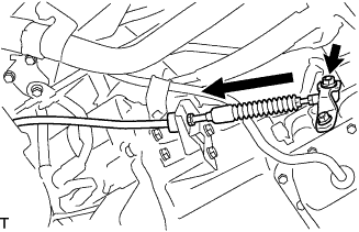
Remove a clip, nut, and disconnect between the control shaft lever to transmission control cable assembly from the control shaft lever and transmission control cable bracket No. 1.
-
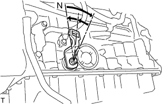
Turn the control shaft lever until stop to a clockwise direction, return the control shaft lever 2 notches to N position.
-
Set the shift lever to N position while holding the shift lever lightly toward the R position side and install it.
15 N*m 150 kgf*cm 11 ft.*lbf -
Inspect the operation condition and work.
-
- Click here
INSPECT SHIFT LEVER POSITION
-
When shifting from P position only with ignition switch ON and depress the break pedal.
-
Make sure that the shifting lever moves smoothly and can be moderately operated.
-
When starting engine, make sure that the vehicle moves forward when shifting from N to D position and moves reward when shifting R position.
-
- Click here
PERFORM INITIALIZATION