- Click here
INSTALL TORQUE CONVERTER ASSEMBLY
-
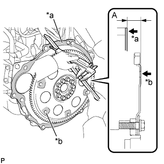
Using a vernier caliper and straightedge, measure dimension A between the automatic transmission assembly contact surface of the engine assembly and the torque converter assembly contact surface of the drive plate.
Table 1. Text in Illustration *a Engine Assembly Surface *b Drive Plate Surface -
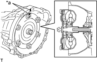
Align the matchmark on the case with the one on the torque converter assembly and engage the splines of the input shaft with the turbine runner splines.
Table 2. Text in Illustration *a Matchmark Note:Install the torque converter assembly to the input shaft while keeping it horizontal.
-
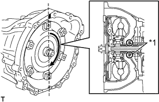
Rotate the torque converter assembly approximately 180° and engage the splines of the stator shaft with the stator assembly.
Table 3. Text in Illustration *1 Front Oil Pump Oil Seal Note:
-
Do not damage the front oil pump oil seal.
-
Install the torque converter assembly to the input shaft while keeping it horizontal.
-
-
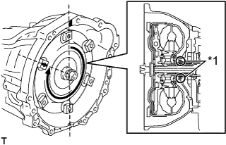
Rotate the torque converter assembly approximately 180° again, align the matchmark on the torque converter assembly with the one on the case and insert the key of the torque converter assembly into the groove of the oil pump drive gear.
Table 4. Text in Illustration *1 Front Oil Pump Oil Seal Note:
-
Do not push the torque converter assembly excessively when rotating it.
-
Do not damage the front oil pump oil seal.
-
Install the torque converter assembly to the input shaft while keeping it horizontal.
-
-
Clean the torque converter set bolt holes.
-
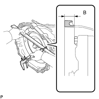
Using a vernier caliper and straightedge, measure dimension B shown in the illustration and check that dimension B is more than dimension A, which was measured in the previous step.
Standard distance B = A + 1.00 mm (0.0394 in.) or more Note:
-
Make sure to deduct the thickness of the straightedge.
-
If the automatic transmission assembly is installed to the engine assembly with the torque converter assembly not sufficiently inserted, the torque converter assembly may be damaged.
-
-
- Click here
INSTALL REAR ENGINE MOUNTING INSULATOR
-
Install the rear engine mounting insulator with the 4 bolts.
29 N*m 296 kgf*cm 21 ft.*lbf
-
- Click here
INSTALL AUTOMATIC TRANSMISSION ASSEMBLY
-
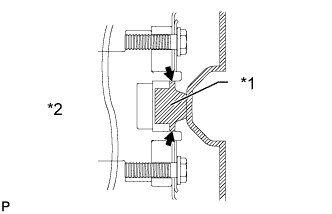
Apply clutch spline grease to the surface of the part of the crankshaft that contacts the torque converter assembly centerpiece.
Clutch spline grease Toyota Genuine Clutch Spline Grease or equivalent Maximum grease amount Approximately 1 g (0.353 oz) Table 5. Text in Illustration *1 Torque Converter Assembly Centerpiece *2 Crankshaft -
Confirm that the 2 knock pins are installed to the engine assembly and are not damaged.
-
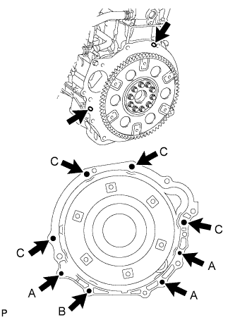
While keeping the engine assembly and automatic transmission assembly horizontal, align the 2 knock pins with the holes in the automatic transmission assembly and install the 8 bolts.
for Bolt A and B 37 N*m 377 kgf*cm 27 ft.*lbf for Bolt C 71 N*m 724 kgf*cm 52 ft.*lbf Note:
-
When tightening the bolts, be sure that the contact surfaces of the engine assembly and the automatic transmission assembly are in close contact with one another.
-
Do not forcibly pry on the automatic transmission assembly.
-
Check that the torque converter assembly rotates.
-
Make sure not to pinch or damage any wire harness.
-
In order to protect the automatic transmission oil pan sub-assembly, place attachments on the transmission jack.
-
Make sure that the attachments and the automatic transmission oil pan sub-assembly are centered on the transmission jack.
-
To prevent the automatic transmission oil pan sub-assembly from deforming, do not place any attachments under the automatic transmission oil pan sub-assembly of the automatic transmission assembly.
-
Secure the automatic transmission assembly to the transmission jack using a belt, etc. to prevent it from falling.
Tip:Bolt length
Bolt A: 40 mm (1.57 in.)
Bolt B and C: 55 mm (2.17 in.)
-
-
- Click here
CONNECT REAR ENGINE MOUNTING INSULATOR ASSEMBLY
-
Install the rear engine mounting insulator assembly with the bolt, nut and 2 washers.
98 N*m 999 kgf*cm 72 ft.*lbf
-
- Click here
INSTALL DRIVE PLATE AND TORQUE CONVERTER SETTING BOLT
-
Turn the crankshaft to gain access to the installation locations of the 6 drive plate and torque converter setting bolts and install each bolt while holding the crankshaft pulley bolt with a wrench.
41 N*m 418 kgf*cm 30 ft.*lbf Note:First install the black colored bolt and then the remaining 5 bolts.
-
Install the flywheel housing dust seal.
-
- Click here
CONNECT WIRE HARNESS
-
Attach the 2 wire harness clamps.
-
Connect the 2 speed sensor connectors and transmission wire connector.
-
Connect the park/neutral position switch assembly connector and ATF temperature sensor connector.
-
- Click here
CONNECT OIL COOLER TUBE
-
Connect the ends of the 2 oil cooler tubes to the automatic transmission assembly by hand.
-
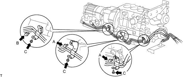
Install the 3 oil cooler tube clamps with the 6 bolts.
for Bolt A 24 N*m 245 kgf*cm 18 ft.*lbf for Bolt B 12 N*m 122 kgf*cm 9 ft.*lbf for Bolt C 8.0 N*m 82 kgf*cm 71 in.*lbf -
Using a 17 mm union nut wrench, install the 2 oil cooler tubes to the automatic transmission assembly.
34 N*m 347 kgf*cm 25 ft.*lbf Note:Use the formula to calculate special torque values for situations where a union nut wrench is combined with a torque wrench (Click here).
-
- Click here
INSTALL TRANSMISSION OIL FILLER TUBE SUB-ASSEMBLY
-
Coat a new O-ring with ATF, and install it to the transmission oil filler tube sub-assembly.
-
Install the transmission oil filler tube sub-assembly with the 2 bolts.
12 N*m 122 kgf*cm 9 ft.*lbf -
Install the oil level dipstick.
-
- Click here
INSTALL TRANSMISSION CONTROL CABLE BRACKET
-
Install the transmission control cable bracket with the 2 bolts.
14 N*m 143 kgf*cm 10 ft.*lbf
-
- Click here
CONNECT TRANSMISSION CONTROL SHIFT CABLE ASSEMBLY
-
Connect the transmission control shift cable assembly with a new clip and nut.
15 N*m 148 kgf*cm 11 ft.*lbf
-
- Click here
INSTALL FRONT EXHAUST PIPE ASSEMBLY
- Click here
INSTALL STARTER ASSEMBLY
- Click here
INSTALL PROPELLER SHAFT ASSEMBLY
- Click here
ADJUST SHIFT LEVER POSITION
-
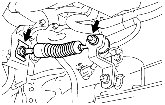
Remove a clip, nut, and disconnect between the control shaft lever to transmission control cable assembly from the control shaft lever and transmission control cable bracket No. 1.
-
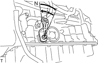
Turn the control shaft lever until stop to a clockwise direction, return the control shaft lever 2 notches to N position.
-
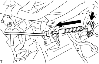
Set the shift lever to N position while holding the shift lever lightly toward the R position side and install it.
15 N*m 150 kgf*cm 11 ft.*lbf -
Inspect the operation condition and work.
-
- Click here
ADD AUTOMATIC TRANSMISSION FLUID
Fluid type Toyota Genuine ATF Type T-IV - Click here
CONNECT CABLE TO NEGATIVE BATTERY TERMINAL
Note:When disconnecting the cable, some systems need to be initialized after the cable is reconnected (Click here).
- Click here
INSTALL TRANSMISSION OIL LEVEL GAUGE SUB-ASSEMBLY
- Click here
INSPECT SHIFT LEVER POSITION
-
When shifting from P position only with ignition switch ON and depress the break pedal.
-
Make sure that the shifting lever moves smoothly and can be moderately operated.
-
When starting engine, make sure that the vehicle moves forward when shifting from N to D position and moves reward when shifting R position.
-
- Click here
CHECK FOR EXHAUST GAS LEAKS
- Click here
CHECK AUTOMATIC TRANSMISSION FLUID LEVEL
- Click here
INSTALL NO. 1 ENGINE UNDER COVER
-
Install the No. 1 engine under cover with the 4 bolts.
13 N*m 133 kgf*cm 10 ft.*lbf
-