МАСЛЯНЫЙ НАСОС УСТАНОВКА

-
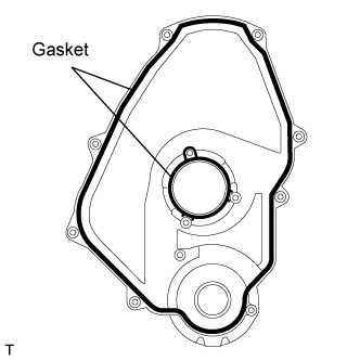
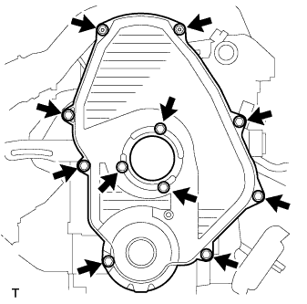
INSTALL TIMING GEAR CASE SUB-ASSEMBLY
-
Place a new gasket on the cylinder block.
-
Install the timing gear case with the 5 bolts.
- Torque:
- 23 N*m { 230 kgf*cm, 17 ft.*lbf }
-
-
INSTALL OIL STRAINER SUB-ASSEMBLY
-
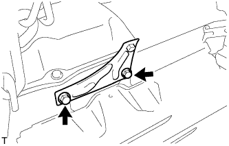
Install a new gasket and oil strainer with the 2 bolts and 2 nuts.
- Torque:
- 21 N*m { 210 kgf*cm, 15 ft.*lbf, for nut }
- 18 N*m { 180 kgf*cm, 13 ft.*lbf, for bolt }
-
-
INSTALL OIL PAN SUB-ASSEMBLY
-
Remove any old packing (FIPG) material and do not drop any oil on the contact surfaces of the oil pan and cylinder block
-
Using a gasket scraper, remove all the old packing (FIPG) material from the installation.
-
Thoroughly clean all components to remove all the loose material.
-
Using a non-residue solvent, clean both sealing surfaces.
Note
Do not use a solvent which will affect the painted surfaces.
-
-
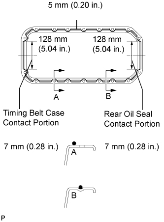
Apply seal packing to the oil pan as shown in the illustration.
Tech Tips
Apply at least 5 mm (0.20 in.) (preferably slightly more) of seal packing to the portions of the oil pan in contact with the timing gear case and rear oil seal retainer.
Seal packing Toyota Genuine Seal Packing Black, Three Bond 1207B or equivalent
-
Apply seal packing with a nozzle with a 4 to 5 mm (0.16 - 0.20 in) opening.
Tech Tips
Do not apply an excessive amount to the surface, especially near the oil passages.
-
Parts must be assembled within 5 minutes of application. Otherwise the material must be removed and reapplied.
-
Immediately remove the nozzle from the tube and reinstall the cap.
-
-
Install the oil pan with the 16 bolts and 2 nuts. Uniformly tighten the bolts and nuts in several steps.
- Torque:
- 18 N*m { 180 kgf*cm, 13 ft.*lbf }
-
-
INSTALL TIMING BELT IDLER SUB-ASSEMBLY NO.2
-
Install the spacer and timing belt idler No.2 with the bolt.
- Torque:
- 33 N*m { 340 kgf*cm, 24 ft.*lbf }
-
Check that the timing belt idler sub-assembly No.2 moves smoothly.
-
-
INSTALL TIMING BELT IDLER SUB-ASSEMBLY NO.1
-
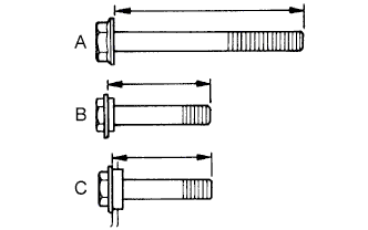
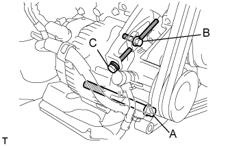
Inspect the 3 bolts.
Tech Tips
-
The bolt lengths for bolt types A, B and C shown in the illustration are:
A 76.5 mm (3.012 in.) B 42.9 mm (1.689 in.), Color : Yellow C 41.3 mm (1.626 in.), Color : Silver -
Bolt C is combined with the timing belt idler sub-assembly No.1.
-
-
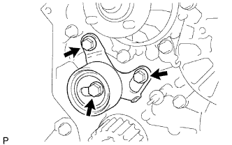
Install the timing belt idler No.1 with the 3 bolts.
- Torque:
- 19 N*m { 195 kgf*cm, 14 ft.*lbf }
-
-
INSTALL CRANKSHAFT TIMING PULLEY
-
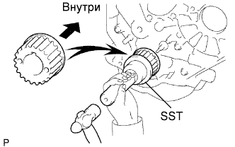
Align the pulley set key with the key groove of the timing pulley.
-
Using SST and a hammer, tap in the timing pulley with the flange side facing inward.
- SST
- 09223-46011
-
-
INSTALL WATER PUMP ASSEMBLY
-
Install a new gasket, the water pump and tension spring bracket with the 6 bolts.
- Torque:
- 23 N*m { 230 kgf*cm, 17 ft.*lbf }
-
-
INSTALL TIMING BELT COVER NO.2
-
Install the timing belt cover with the 4 bolts.
- Torque:
- 18 N*m { 185 kgf*cm, 13 ft.*lbf }
-
-
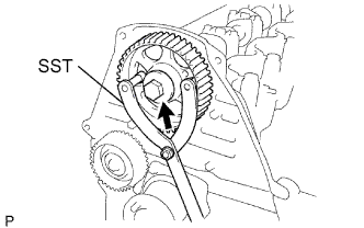
INSTALL CAMSHAFT TIMING PULLEY
-
Install the woodruff key to the key groove of the camshaft.
-
Align the pulley set key with the timing mark outward.
-
Using SST, install the pulley with the bolt.
- Torque:
- 98 N*m { 1,000 kgf*cm, 72 ft.*lbf }
-
-
INSTALL INJECTION PUMP
-
Install the injection or supply pump assembly to timing gear case, and temporarily tighten the 2 nuts.
-
Install injection pump stay No.1 to the injection or supply pump assembly rear end, and temporarily tighten the 3 bolts.
-
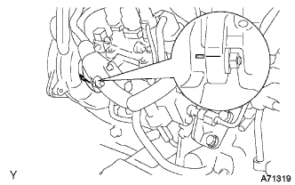
Rotate the pump body to make the marking of pump flange conform to the making of timing of gear case.
-
Tighten the 2 nuts to install the injection or supply pump assembly.
- Torque:
- 21 N*m { 210 kgf*cm, 15 ft.*lbf }
-
Tighten the 3 bolts to install the injection pump stay No.1.
- Torque:
- Injection pump stay No.1 x Cylinder Block
- 21 N*m { 210 kgf*cm, 15 ft.*lbf }
- Injection pump stay No.1 x Injection Pump
- 18 N*m { 185 kgf*cm, 13 ft.*lbf }
-
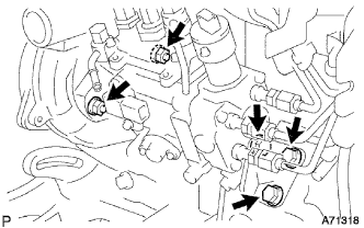
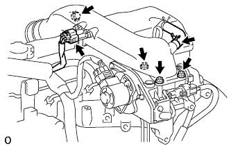
Connect the 3 fuel hoses.
-
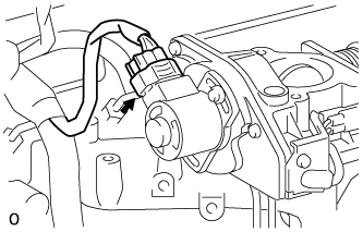
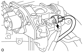
Connect the engine speed sensor connector.
-
Connect the spill control valve connector.
-
Connect the correction unit connector.
-
Connect the timer control valve connector.
-
Connect the fuel temperature sensor connector.
-
Connect the engine wire clamp.
-
-
SET NO.1 CYLINDER TO TDC/COMPRESSION
-
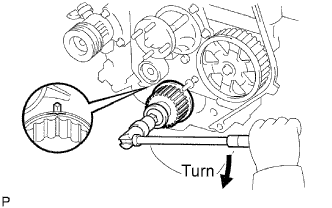
Using the crankshaft pulley bolt, align its groove with the timing pointer by turning the crankshaft clockwise.
Note
Do not turn the crankshaft pulley counterclockwise.
-
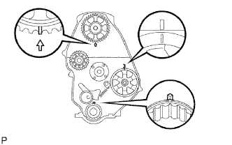
Set the timing and drive pulleys at each position.
Note
-
The engine should be cold.
-
When turning the crankshaft or camshaft, the valve heads will hit against the piston top. Do not turn them more than necessary.
-
-
-
INSTALL TIMING BELT
Tech Tips
If reusing the timing belt, align the points marked during removal, and install the timing belt with the arrow pointing in the direction of engine revolution.
-
Remove any oil or water on each pulleys, and keep them clean.
-
Install the timing belt on the crankshaft timing pulley and timing belt idlers.
-
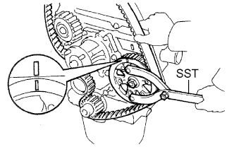
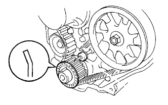
Using SST, slightly turn the injection pump drive pulley clockwise. Hang the timing belt on the pulley, and align the timing marks of the drive pulley and timing belt case.
- SST
- 09960-10010 ( 09962-01000, 09963-01000 )
-
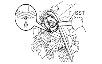
Using SST, slightly turn the camshaft timing pulley clockwise. Hang the timing belt on the timing pulley, and align the timing marks of the timing pulley and timing belt case.
- SST
- 09960-10010 ( 09962-01000, 09963-01000 )
-
Check that the timing belt has tension between the injection pump drive and camshaft timing pulleys.
-
Install the timing belt on the timing belt idler No.2.
-
-
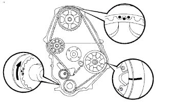
CHECK VALVE TIMING
-
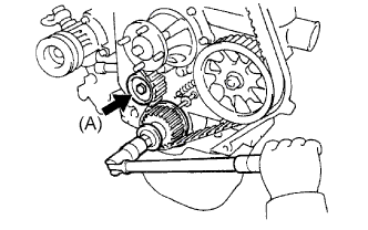
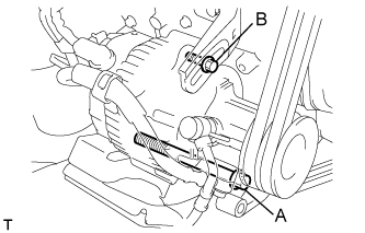
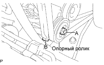
Loosen the timing belt idler No.1 bolt (A), and stretch the timing belt.
-
Slowly turn the crankshaft pulley 2 revolutions from TDC to TDC.
Note
Always turn the crankshaft clockwise.
-
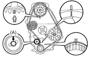
Check each pulley aligns with the timing marks as shown in the illustration.
If the timing marks do not align, remove the timing belt and reinstall it.
-
Tighten the timing belt idler No.1 bolt (A).
- Torque:
- 44 N*m { 450 kgf*cm, 33 ft.*lbf }
-
-
INSTALL TIMING BELT GUIDE
-
Install the belt guide with the cup side facing outward.
-
-
INSTALL TIMING CHAIN OR BELT COVER SUB-ASSEMBLY
-
Remove the 2 nuts and wire harness clamp bracket.
-
Install the 2 gaskets to the timing belt cover.
-
Install the timing belt cover with the 11 bolts.
- Torque:
- 11 N*m { 105 kgf*cm, 8 ft.*lbf }
-
Install the 2 nuts and wire harness clamp bracket.
-
-
INSTALL CRANKSHAFT PULLEY
-
Align the pulley set key with the key groove of the timing pulley.
-
Using SST and a hammer, tap in the timing pulley with the flange side facing inward.
- SST
- 09223-46011
-
-
INSTALL VANE PUMP DRIVE PULLEY
-
w/o Air conditioning:
-
Install the vane pump drive pulley and vane pump pulley spacer with the 4 bolts.
- Torque:
- 19 N*m { 195 kgf*cm, 14 ft.*lbf }
-
-
w/ Air conditioning:
-
Install the 2 vane pump drive pulleys with the 4 bolts.
- Torque:
- 18 N*m { 184 kgf*cm, 13 ft.*lbf }
-
-
-
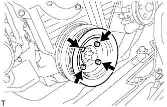
INSTALL COMPRESSOR MOUNTING BRACKET (w/ Air Conditioning System)
-
Temporarily install the compressor mounting bracket with the 4 bolts.
-
Using several steps, uniformly install and tighten the 4 bolts in the sequence shown in the illustration.
- Torque:
- 85 N*m { 870 kgf*cm, 63 ft.*lbf }
-
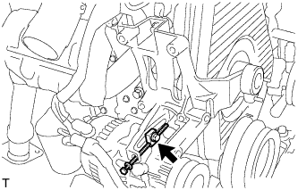
Temporarily tighten the bolt and spacer.
-
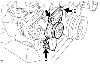
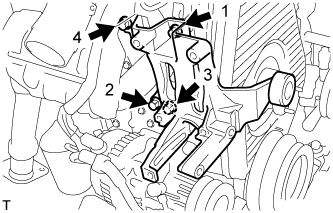
Temporarily install the compressor mounting bracket with the 3 bolts.
-
Using several steps, uniformly install and tighten the 3 bolts in the sequence shown in the illustration.
- Torque:
- 47 N*m { 475 kgf*cm, 36 ft.*lbf }
-
-
INSTALL COMPRESSOR AND MAGNETIC CLUTCH (w/ Air Conditioning System)
-
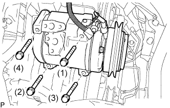
Установите компрессор и электромагнитную муфту и закрепите их 4 болтами.
- Torque:
- 25 Н*м { 255 кгс*см, 18 фунт-сила-футов }
Note
При установке компрессора и электромагнитной муфты затягивайте болты в последовательности, показанной на рисунке.
-
-
INSTALL INJECTION PIPE SET
-
Connect the 2 lower clamps on the intake manifold.
-
Install the 4 injection pipes.
- Torque:
- 25 N*m { 250 kgf*cm, 18 ft.*lbf }
-
Secure the injection pipes with the 2 upper pipe clamps and 2 nuts.
- Torque:
- 5.0 N*m { 50 kgf*cm, 44 in.*lbf }
-
-
INSTALL VENTURI ASSEMBLY
-
Install a new gasket and venturi.
-
Connect the throttle control motor connector.
-
Connect the throttle open switch connector.
-
-
INSTALL INTAKE AIR CONNECTOR BRACKET
-
Install the 2 bolts and intake air connector bracket.
- Torque:
- 18 N*m { 184 kgf*cm, 13 ft.*lbf }
-
-
INSTALL INTAKE AIR CONNECTOR SUB-ASSEMBLY
-
Install a new gasket and intake air connector with the bolt and 3 nuts.
- Torque:
- bolt
- 18 N*m { 184 kgf*cm, 13 ft.*lbf }
- Nut
- 12 N*m { 122 kgf*cm, 9 ft.*lbf }
-
Connect the turbo pressure sensor connector.
-
Connect the ventilation hose.
-
-
INSTALL WATER PUMP PULLEY
-
INSTALL FAN & GENERATOR V BELT (w/o Air Conditioning)
-
Установите поликлиновой ремень.
-
Отрегулируйте натяжение поликлинового ремня с помощью стержня.
-
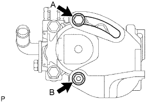
Затяните болты А и В.
- Torque:
- Болт A
- 75 Н*м { 765 кгс*см, 55 фунт-сила-фута }
- Болт B
- 18 Н*м { 185 кгс*см, 13 фунт-сила-футов }
-
Проверьте натяжение поликлинового ремня. (см. стр. Click here)
-
-
INSTALL FAN & GENERATOR V BELT (w/ Air Conditioning)
-
Установите поликлиновой ремень.
-
Отрегулируйте натяжение поликлинового ремня с помощью болта C.
-
Затяните болты А и В.
- Torque:
- Болт A
- 75 Н*м { 765 кгс*см, 55 фунт-сила-футов }
- Болт B
- 18 Н*м { 185 кгс*см, 13 фунт-сила-футов }
-
Проверьте натяжение поликлинового ремня. (см. стр. Click here)
-
-
INSTALL V (COOLER COMPRESSOR TO CRANKSHAFT PULLEY) BELT NO.1 (w/ Air Conditioning System)
-
Установите поликлиновой ремень.
-
Затягивая болт В, отрегулируйте натяжение поликлинового ремня.
-
Затяните гайку А.
- Torque:
- 39 Н*м { 400 кгс*см, 29 фунт-сила-футов }
-
Проверьте натяжение поликлинового ремня. (см. стр. Click here)
-
-
INSTALL VANE PUMP V BELT
-
Установите поликлиновой ремень.
-
Отрегулируйте натяжение поликлинового ремня с помощью стержня.
-
Затяните болт А и гайку В.
- Torque:
- Болт (A)
- 48 Н*м { 489 кгс*см, 35 фунт-сила-футов }
- Гайка (B)
- 64 Н*м { 635 кгс*см, 47 фунт-сила-дюймов }
-
Проверьте натяжение поликлинового ремня. (см. стр. Click here)
-
-
BLEED INJECTION PIPE
-
Move the priming pump in the upper part of the fuel filter assembly up and down, and fill the injection pump assembly and fuel system with fuel.
-
Loosen one of the union nuts (in the nozzle side).
-
Crank the engine until fuel comes out from the union nut (in the nozzle side).
-
Tighten the union nut.
- Torque:
- 25 N*m { 250 kgf*cm, 18 ft.*lbf }
-
The above operation should be carried out each injection pipe.
-
-
CONNECT WATER HOSE (for Heater)
-
INSTALL RADIATOR HOSE NO.4
-
INSTALL RADIATOR HOSE INLET
-
ADD ENGINE COOLANT
-
Залейте охлаждающую жидкость в расширительный бачок радиатора до верха горловины.
Номинальный объем Параметр / Устройство Заданные условия Для моделей без подогревателя 12,3 литра (13,0 кварты США, 10,8 английской кварты) Для моделей с передним подогревателем 13,3 литра (14,1 кварты США, 11,7 английской кварты) Для моделей с передним и задним подогревателями 15,3 литра (16,2 кварты США, 13,5 английской кварты) Note
Не доливайте простую воду вместо охлаждающей жидкости двигателя.
Tech Tips
-
Использование неподходящей охлаждающей жидкости может привести к повреждению системы охлаждения двигателя.
-
Разрешается использовать только охлаждающую жидкость "TOYOTA Super Long Life Coolant" или аналогичную высококачественную охлаждающую жидкость на основе этиленгликоля (а не на силикатной, аминовой, нитритной или борнокислой основе), изготовленную по гибридной технологии органических кислот с длительным сроком годности (охлаждающая жидкость, изготовленная по гибридной технологии органических кислот, состоит из низкофосфатных соединений и органических кислот).
-
-
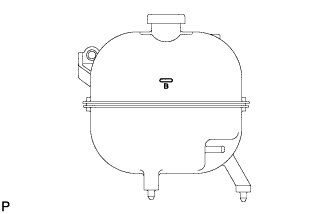
Долейте охлаждающую жидкость в расширительный бачок радиатора до отметки B и установите пробку расширительного бачка радиатора.
-
Прогревайте двигатель, пока не откроется термостат.
-
Когда термостат откроется, несколько минут прокачивайте охлаждающую жидкость.
Tech Tips
Время открывания термостата можно проверить, сжав входной патрубок радиатора рукой и убедившись, что охлаждающая жидкость поступает в шланг.
-
-
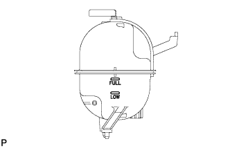
После охлаждения двигателя убедитесь, что уровень охлаждающей жидкости находится между отметками "LOW" и "FULL".
-
-
ADD ENGINE OIL
-
CHECK FOR ENGINE OIL LEAKS
-
CHECK FOR ENGINE COOLANT LEAKS
CAUTION:
Не снимайте пробку радиатора, пока двигатель и радиатор не остынут. Выброс горячей охлаждающей жидкости и пара под давлением может стать причиной серьезных ожогов.
-
Заполните радиатор охлаждающей жидкостью и подсоедините к радиатору приспособление для опрессовки системы охлаждения и проверки пробки радиатора.
-
Прогрейте двигатель.
-
С помощью приспособления для опрессовки системы охлаждения и проверки пробки радиатора увеличьте давление в радиаторе до 118 кПа (1,2 кгс/см2, 17,1 фунтов на кв. дюйм) и убедитесь, что давление не падает.
Tech Tips
Если давление снижается, проверьте на наличие утечек шланги, радиатор и насос системы охлаждения. При отсутствии внешних утечек проверьте сердцевину отопителя, блок цилиндров и головку блока цилиндров.
-
-
CHECK FOR FUEL LEAKS
-
Check that there are no fuel leaks anywhere on the fuel system after doing maintenance.
Tech Tips
When checking for fuel leaks, make sure that there is pressure in the fuel line.
-
-
INSTALL ENGINE SERVICE HOLE SUB COVER SUB-ASSEMBLY
-
Install the 5 bolts and engine service hole cover.
- Torque:
- 13 N*m { 133 kgf*cm, 10 ft.*lbf }
-
-
INSTALL FRONT DOOR SCUFF PLATE RH
-
INSTALL FRONT SEAT ASSEMBLY RH
-
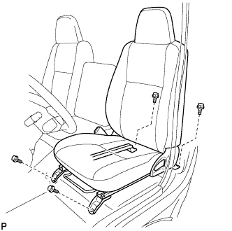
Подсоедините разъем замка ремня безопасности переднего сиденья в сборе и установите переднее сиденье в сборе.
-
Совместите штырь регулятора переднего сиденья в сборе с отверстиями в кузове.
-
Сдвиньте переднее сиденье в сборе в крайнее заднее положение.
Note
Убедитесь, что переднее сиденье в сборе надежно зафиксировано.
-
Предварительно затяните 2 болта на передней стороне переднего сиденья в сборе.
-
Выдвиньте переднее сиденье в сборе до упора вперед.
Note
Убедитесь, что переднее сиденье в сборе надежно зафиксировано.
-
Предварительно затяните 2 болта на задней стороне переднего сиденья в сборе.
-
Сдвиньте переднее сиденье в сборе в крайнее заднее положение.
Note
Убедитесь, что переднее сиденье в сборе надежно зафиксировано.
-
Полностью затяните 2 болта на передней стороне переднего сиденья в сборе, сначала наружный, а затем внутренний.
- Torque:
- 39 Н*м { 398 кгс*см, 29 фунт-сила-футов }
-
Выдвиньте переднее сиденье в сборе до упора вперед.
Note
Убедитесь, что переднее сиденье в сборе надежно зафиксировано.
-
Полностью затяните 2 болта на задней стороне переднего сиденья в сборе, сначала наружный, а затем внутренний.
- Torque:
- 39 Н*м { 398 кгс*см, 29 фунт-сила-футов }
-