МАСЛЯНЫЙ НАСОС ПРОВЕРКА
-
INSPECT TIMING BELT
-
INSPECT TIMING BELT IDLER SUB-ASSEMBLY NO.1
-
INSPECT IDLER TENSION SPRING
-
INSPECT WATER PUMP ASSEMBLY
-
INSPECT OIL PUMP RELIEF VALVE
-
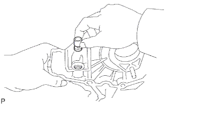
Coat the valve with engine oil and check that it falls smoothly into the valve hole by its own weight.
-
If it does not fall smoothly into the valve hole, replace the relief valve. If necessary, replace the oil pump assembly.
-
-
-
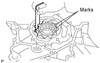
INSPECT OIL PUMP DRIVE GEAR
-
Install the rotors to the timing gear case sub-assembly with the rotors marks facing outward. Check that the rotors revolves smoothly.
-
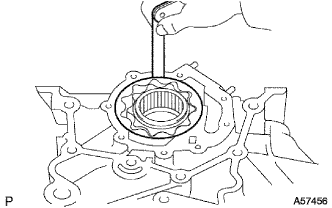
Inspect the gear tip clearance.
-
Using a feeler gauge, measure the clearance between the drive and driven gear tips.
Standard tip clearance 0.110 to 0.240 mm (0.0043 to 0.0094 in.) Maximum tip clearance 0.30 mm (0.0118 in.)
-
If the tip clearance is greater than the maximum, replace the gears as a set.
-
-
-
Inspect the gear body clearance.
-
Using a feeler gauge, measure the clearance between the driven gear and timing gear case.
Standard body clearance 0.144 to 0.219 mm (0.0057 to 0.0086 in.) Maximum body clearance 0.40 mm (0.0157 in.)
-
If the body clearance is greater than the maximum, replace the gears as a set. If necessary, replace the oil pump assembly.
-
-
-
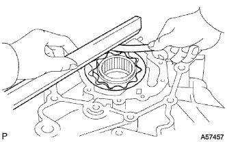
Inspect the gear side clearance.
-
Using a feeler gauge and precision straight edge, measure the clearance between the gears and precision straight edge.
Standard side clearance 0.035 to 0.085 mm (0.0014 to 0.0033 in.) Maximum side clearance 0.15 mm (0.0059 in.)
-
If the side clearance is greater than the maximum, replace the gears as a set. If necessary, replace the oil pump assembly.
-
-
-