МАСЛЯНЫЙ РАДИАТОР ДВИГАТЕЛЯ СНЯТИЕ

-
DISCONNECT CABLE FROM NEGATIVE BATTERY TERMINAL
-
REMOVE ENGINE UNDER COVER NO.1 (w/ Engine Under Cover No.1)
-
DRAIN ENGINE COOLANT
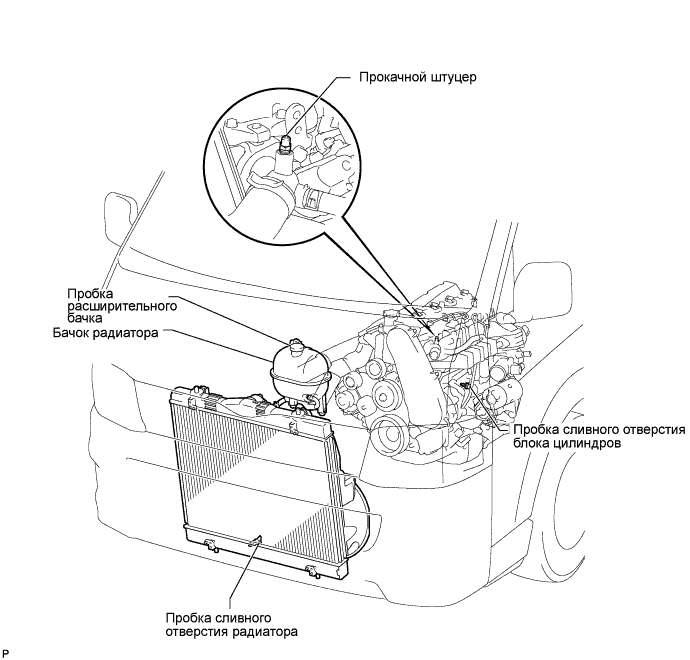
CAUTION:
Для предотвращения ожогов не снимайте пробку расширительного бачка, пока двигатель и радиатор не охладятся. Тепловое расширение вызывает выброс из радиатора горячей охлаждающей жидкости и пара.
-
Ослабьте пробку сливного отверстия радиатора.
-
Снимите пробку расширительного бачка.
-
Ослабьте пробку сливного отверстия блока цилиндров (на крышке масляного радиатора двигателя) и слейте охлаждающую жидкость.
-
Затяните пробку сливного отверстия радиатора.
-
Затяните пробку сливного отверстия блока цилиндров (на крышке масляного радиатора двигателя).
- Torque:
- 8,0 Н*м { 82 кгс*см, 71 фунт-сила-дюйм }
-
-
REMOVE BATTERY SERVICE HOLE COVER
-
REMOVE FRONT SEAT ASSEMBLY RH (for Hi-back Seat Type)
Tech Tips
Use the same procedures described for the LH side. Click here
-
REMOVE FRONT SEAT ASSEMBLY RH (for Low-back Seat Type)
Tech Tips
Use the same procedures described for the LH side. Click here
-
REMOVE FRONT DOOR SCUFF PLATE RH
-
REMOVE ENGINE SERVICE HOLE SUB COVER SUB-ASSEMBLY
-
Заверните коврик и снимите вспомогательную крышку технологического отверстия двигателя.
-
-
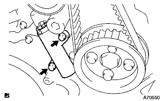
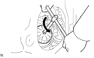
REMOVE FAN & GENERATOR V BELT
-
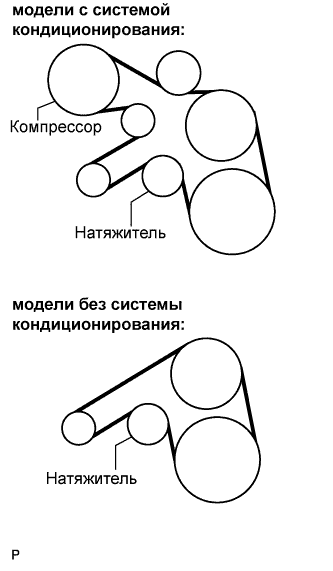
Снимите приводной ремень, повернув шкив натяжителя по часовой стрелке с помощью установочного болта шкива, чтобы ослабить натяжение ремня.
-
-
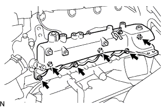
REMOVE TIMING BELT COVER NO.1
-
Remove the wire harness clamp.
-
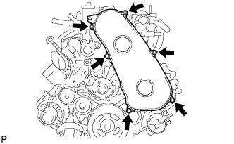
Remove the 6 bolts and timing belt cover No.1.
-
-
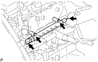
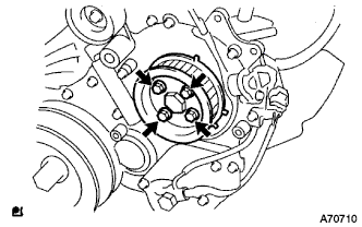
REMOVE TIMING BELT
-
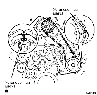
Turn the crankshaft in the clockwise direction and align the timing marks as shown in the illustration.
-
Uniformly loosen the 2 bolts, and remove the chain tensioner assembly No.1.
-
Remove the timing belt.
-
-
SEPARATE VANE PUMP OIL RESERVOIR ASSEMBLY
-
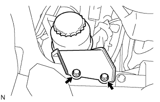
Отверните 2 болта. Отсоедините масляный бачок лопастного насоса в сборе.
-
-
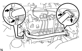
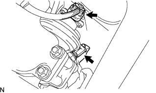
SEPARATE OIL RETURN HOSE (w/ Intercooler)
-
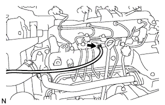
Ослабьте фиксатор.
-
Отсоедините возвратный масляный шланг от впускного коллектора.
-
-
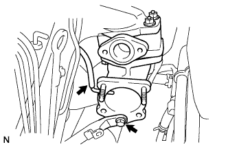
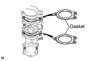
REMOVE EGR PIPE SUB-ASSEMBLY NO.1 (w/ EGR Valve)
-
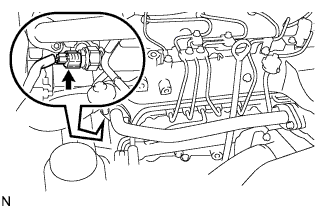
Отсоедините разъем датчика давления в топливной системе.
-
Выверните 2 болта, отверните 2 гайки и снимите трубу РОГ.
-
Снимите 2 прокладки.
-
-
REMOVE AIR HOSE NO.4
-
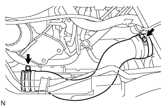
Ослабьте 2 зажима.
-
Снимите воздушный шланг № 4.
-
-
REMOVE DIESEL THROTTLE BODY ASSEMBLY
-
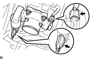
Отсоедините 2 разъема корпуса дроссельной заслонки.
-
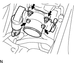
Выверните 2 болта, отверните 2 гайки и снимите корпус дроссельной заслонки дизельного двигателя в сборе.
-
Снимите прокладку с патрубка подачи воздуха.
-
-
REMOVE ENGINE SERVICE HOLE COVER NO.2
-
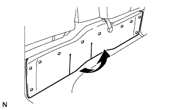
Roll up the carpet.
-
Remove the 3 bolts and the engine service hole cover No.2.
-
-
REMOVE INTAKE AIR CONNECTOR (w/o EGR Valve)
-
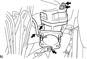
Remove the bolt, and separate the manifold stay.
-
Disconnect the vacuum hose from intake air connector.
-
Remove the bolt, 2 nuts and the intake air connector assembly.
-
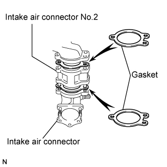
Remove the 2 gaskets and intake air connector No.2 from the intake air connector.
-
-
REMOVE ELECTRIC EGR CONTROL VALVE ASSEMBLY (w/ EGR Valve)
-
Remove the vacuum regulating valve.
-
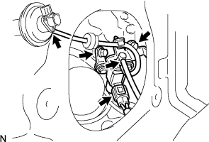
Remove the 2 vacuum hoses and the vacuum regulating valve connector.
-
Remove the 2 bolts and the vacuum regulating valve.
-
-
Remove the EGR valve assembly with the sensor.
-
Remove the bolt, and separate the manifold stay.
-
Disconnect the vacuum hose from the intake air connector.
-
Disconnect the intake air temperature sensor connector.
-
Disconnect the EGR valve position sensor connector.
-
Remove the bolt, 2 nuts and the intake air connector assembly.
-
Remove the 2 gaskets and EGR valve assembly from the intake air connector.
-
-
-
REMOVE OIL LEVEL GAUGE GUIDE
-
Снимите щуп проверки уровня масла.
-
Выверните болт и снимите трубку щупа проверки уровня масла.
-
-
REMOVE INJECTION PIPE SUB-ASSEMBLY
- SST
- 09023-12701
-
Remove the injection pipe.
-
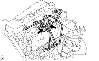
Remove the 2 nuts and injection pipe clamp No.3.
-
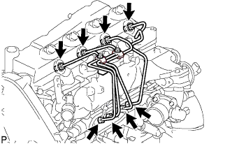
Using SST, remove the 4 injection pipes.
- SST
- 09023-12701
-
-
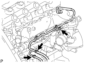
REMOVE FUEL INLET PIPE SUB-ASSEMBLY
-
Using SST, remove the fuel inlet pipe sub-assembly.
- SST
- 09023-12701
-
-
REMOVE NOZZLE LEAKAGE PIPE ASSEMBLY NO.2
-
Disconnect 3 fuel hoses from nozzle leakage pipe assembly No.2.
-
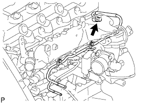
Remove the union bolt from nozzle leakage pipe No.2.
-
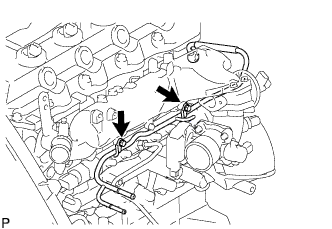
Remove the 2 bolts and nozzle leakage pipe No.2.
-
Remove the gasket from nozzle leakage pipe No.2.
-
-
REMOVE INTAKE MANIFOLD
-
Remove the bolt, nut, and the manifold stay.
-
Remove the bolt, and disconnect the ground cable.
-
Remove the 4 bolts, 2 nuts, and intake manifold.
-
Remove the gasket from the cylinder head.
-
-
REMOVE OIL FILTER SUB-ASSEMBLY
-
Using SST, remove the oil filter.
- SST
- 09228-07501
Tech Tips
Position the drain oil container to collect the oil from the oil filter.
-
-
REMOVE COMMON RAIL ASSEMBLY
-
Disconnect the fuel pressure sensor connector from the common rail assembly.
-
Disconnect the fuel hose from the fuel pressure limiter.
-
Remove the 2 bolts and common rail assembly.
-
-
REMOVE INJECTION OR SUPPLY PUMP ASSEMBLY
-
Remove the 4 bolts.
-
Remove the camshaft timing pulley flange No.2 and pump drive shaft pulley.
-
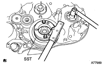
Using SST, remove the supply pump gear set nut and O-ring while holding the crankshaft pulley.
- SST
- 09213-58013
- 09330-00021
-
Disconnect the 2 fuel hoses.
-
Disconnect the 2 connectors and wire harness.
-
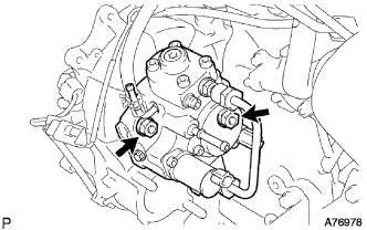
Loosen the 2 nuts as shown in the illustration.
-
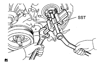
Using SST, disengage the supply pump from the supply pump gear.
- SST
- 09950-50013 ( 09951-05010, 09952-05010, 09953-05020, 09954-05021 )
-
Remove the 2 nuts and supply pump from the engine.
-
Remove the O-ring from the supply pump.
-
Remove the pulley key from the supply pump.
-
-
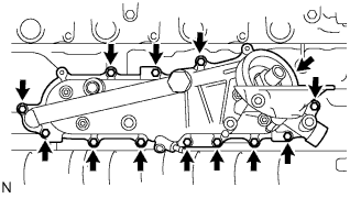
REMOVE OIL COOLER COVER SUB-ASSEMBLY (w/o EGR Valve)
-
Disconnect the oil pressure switch connector.
-
Disconnect the oil filter drain hoses.
-
Remove the 2 nuts, 13 bolts, oil cooler cover, and gasket.
-
-
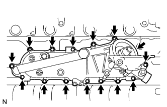
REMOVE OIL COOLER COVER SUB-ASSEMBLY (w/ EGR Valve)
-
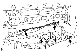
Disconnect the oil pressure switch connector.
-
Disconnect the oil filter drain hoses.
-
Remove the 2 nuts and the vacuum transmitting pipe No.2 from the oil cooler cover.
-
Remove the 13 bolts, oil cooler cover, and gasket.
-
-
REMOVE OIL COOLER ASSEMBLY
-
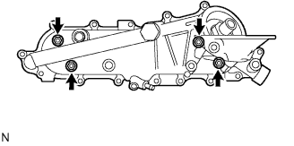
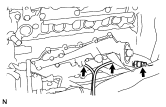
Loosen the 4 nuts until they are flush with the end of the bolts.
-
Using a plastic hammer, uniformly tap the end of the nuts to separate the oil cooler cover and oil cooler assembly.
-
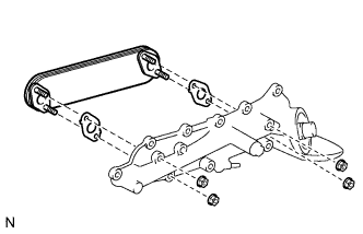
Remove the 4 nuts, oil cooler assembly, and 2 gaskets from the oil cooler cover.
-