- Click here
INSPECT LOCK PLATE FOR DAMAGE
-
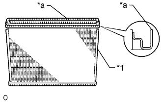
Inspect the lock plate for damage.
Table 1. Text in Illustration *1 Core *a Lock Plate If the sides of the lock plate groove are deformed, reassembly of the tank will be impossible. Correct any deformations with pliers.
Water will leak if the bottom of the lock plate groove is damaged or dented. Repair or replace it as necessary.
Note:The radiator can only be recaulked twice. After the second time, the radiator core must be replaced.
-
- Click here
INSTALL UPPER RADIATOR TANK
-
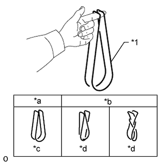
Check that there are no foreign objects in the lock plate groove, and install a new O-ring. Make sure the O-ring is not twisted.
Table 2. Text in Illustration *1 O-Ring *a CORRECT *b INCORRECT *c Normal *d Twisted Tip:When cleaning the lock plate groove, lightly rub it with sandpaper without scratching it.
-
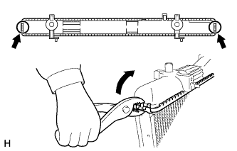
Install the tank without damaging the O-ring.
-
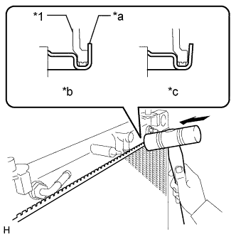
Lightly tap the lock plate with a plastic-faced hammer so that there is no gap between the lock plate and the tank.
Table 3. Text in Illustration *1 Tank *a Lock Plate *b CORRECT *c INCORRECT
-
- Click here
INSTALL LOWER RADIATOR TANK
Tip:Use the same procedure described for the upper radiator tank.
- Click here
ASSEMBLE SST
-
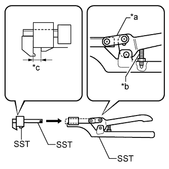
Install the punch assembly to part A of the overhaul handle as shown in the illustration.
09230-01010 09231-01010 09231-01020 09231-14010 Table 4. Text in Illustration *a Part A *b Stopper Bolt *c Dimension B -
While squeezing the handle, adjust the stopper bolt so that dimension B is as specified below.
Dimension B 8.4 mm (0.331 in.)
-
- Click here
CAULK LOCK PLATE
-
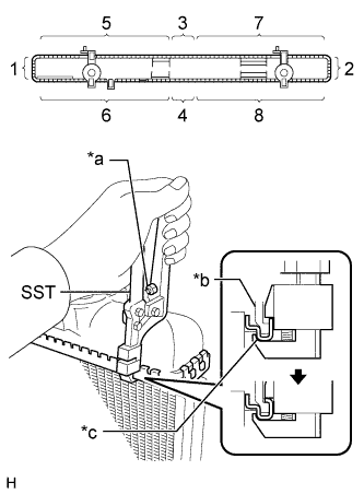
Lightly press SST and pliers against the lock plate in the order shown in the illustration. Repeat this step a few times, and then fully caulk the lock plate by squeezing the handle until stopped by the stopper bolt.
09230-01010 09231-01010 09231-01020 09231-14010 Table 5. Text in Illustration *a Stopper Bolt *b Tank *c Lock Plate Note:
-
Do not press the protruding areas around the ports.
-
Do not use SST to press the areas indicated by the circle marks in the illustration. Use pliers and be careful not to damage the core plates.
-
-
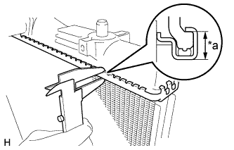
Check the lock plate height after completing the caulking.
Standard plate height 8.6 mm (0.333 in.) Table 6. Text in Illustration *a Lock Plate Height If the height is not as specified, readjust the stopper bolt of the handle and caulk the lock plate again.
-
- Click here
INSTALL LOWER NO. 2 RADIATOR TANK PIPE
-
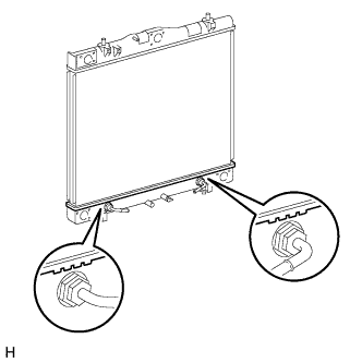
Install the lower No. 2 radiator tank pipe, and slide the hose clamp to secure the pipe.
-
Connect the lower No. 2 radiator tank pipe to the radiator assembly with the bolt.
6.0 N*m 61 kgf*cm 53 in.*lbf
-
- Click here
INSTALL LOWER NO. 1 RADIATOR TANK PIPE
-
Install a new O-ring to the lower No. 1 radiator tank pipe.
-
Install the lower No. 1 radiator tank pipe with the 3 bolts.
6.0 N*m 61 kgf*cm 53 in.*lbf
-
- Click here
INSTALL UPPER RADIATOR TANK PIPE
-
Install a new O-ring to the radiator upper tank pipe.
-
Install the upper radiator tank pipe with the 3 bolts.
6.0 N*m 61 kgf*cm 53 in.*lbf
-
- Click here
INSTALL RADIATOR DRAIN COCK PLUG
-
Install a new O-ring to the drain cock plug.
-
Install the drain cock plug.
-