НАСОС СИСТЕМЫ ОХЛАЖДЕНИЯ УСТАНОВКА

-
INSTALL WATER PUMP ASSEMBLY
-
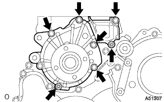
Install a new gasket and the water pump with the 5 bolts and 2 nuts.
- Torque:
- 13 N*m { 133 kgf*cm, 10 ft.*lbf }
-
-
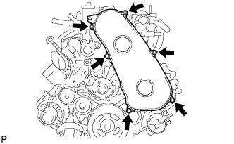
INSTALL TIMING BELT COVER NO.2
-
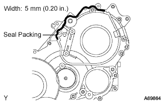
Remove old seal packing (FIPG) from the timing gear case.
-
Apply seal packing to the specific places shown in the illustration.
Seal packing Toyota Genuine Seal Packing Black, Three Bond 1207B or equivalent Note
-
After applying FIPG, install the timing belt No.2 cover within 3 minutes and tighten its bolts and nuts within 15 minutes.
-
Do not start the engine 2 hours after the installation.
-
-
Fix the timing belt cover No.2 with the 4 bolts and nuts.
- Torque:
- 10 N*m { 102 kgf*cm, 7 ft.*lbf }
-
-
INSTALL TIMING BELT IDLER SUB-ASSEMBLY NO.1
-
Using a 10 mm socket hexagon wrench, install the new plate washer and timing belt idler No.1.
- Torque:
- 35 N*m { 357 kgf*cm, 26 ft.*lbf }
-
-
INSTALL CAMSHAFT TIMING PULLEY
-
Install the camshaft timing pulley.
-
Tighten the bolt for the camshaft timing pulley while holding the camshaft with a monkey wrench.
- Torque:
- 98 N*m { 1,000 kgf*cm, 72 ft.*lbf }
-
-
INSTALL CYLINDER HEAD COVER SUB-ASSEMBLY
-
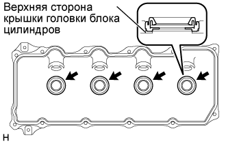
Install 4 new No. 3 cylinder head cover gaskets to the cylinder head cover as shown in the illustration.
Note
-
Do not install the gaskets at an angle.
-
Keep the lip of the gasket free from foreign materials.
-
-
Install a new cylinder head cover gasket to the cylinder head cover.
-
Remove old seal packing (FIPG) from the cylinder head.
-
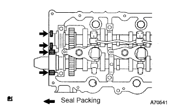
Apply a seal packing to the specific places described in the illustration.
Seal packing Toyota Genuine Seal Packing Black, Three Bond 1207B or equivalent Note
-
After applying the seal packing, parts must be assembled within 3 minutes, and then tighten within 15 minutes.
-
Otherwise the material must be removed and reapplied.
-
Do not start the engine 2 hour after the installation.
-
-
Install the cylinder head cover with 10 bolts and 2 nuts.
- Torque:
- 9.0 N*m { 92 kgf*cm, 80 in.*lbf }
-
Connect the ventilation hose.
-
Install a new nozzle holder seal.
-
-
INSTALL FUEL INLET PIPE SUB-ASSEMBLY
Note
-
When replacing the fuel supply pump, common rail, cylinder block, cylinder head, cylinder head gasket, or timing gear case with a new one, replace the fuel inlet pipe.
-
Be careful not to adhere dusts, dirt or any other materials onto the joint area of the fuel inlet pipe.
-
Temporarily install the fuel inlet pipe.
-
Using SST, tighten the injection pipe on the common rail side.
- SST
- 09023-12701
- Torque:
- 32 N*m { 326 kgf*cm, 24 ft.*lbf, for use with SST }
-
Using SST, tighten the injection pipe on the supply pump side.
- SST
- 09023-12701
- Torque:
- 32 N*m { 326 kgf*cm, 24 ft.*lbf, for use with SST }
-
-
INSTALL INJECTION PIPE
- SST
- 09023-12701
Note
-
When replacing the fuel injector, common rail, or cylinder head with a new one, replace injection pipes No. 1, No. 2, No. 3, and No. 4.
-
Keep clean the joint of the injection pipe.
-
Install the injection pipes.
-
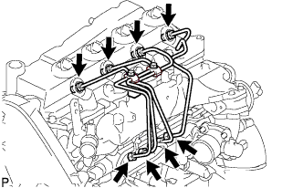
Temporarily install the 4 injection pipes.
-
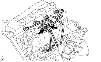
Install the injection pipe clamp No.3 in 2 nuts.
- Torque:
- 5.0 N*m { 51 kgf*cm, 44 in.*lbf }
-
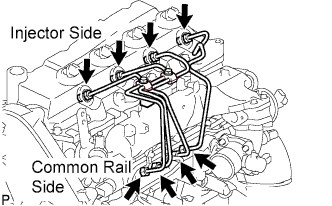
Fasten the union sequentially, from the injection pipe common rail to the injector, using SST.
- SST
- 09023-12701
- Torque:
- Use union nut wrench and torque wrench
- 32 N*m { 326 kgf*cm, 24 ft.*lbf }
-
-
INSTALL OIL LEVEL GAGE GUIDE
-
Установите на трубку щупа проверки уровня масла новое уплотнительное кольцо.
-
Нанесите на уплотнительное кольцо тонкий слой моторного масла.
-
Установите трубку щупа проверки уровня масла и закрепите ее болтом.
- Torque:
- 8,0 Н*м { 82 кгс*см, 71 фунт-сила-дюйм }
-
Установите щуп проверки уровня масла.
-
-
INSTALL INTAKE AIR CONNECTOR (w/o EGR Valve)
-
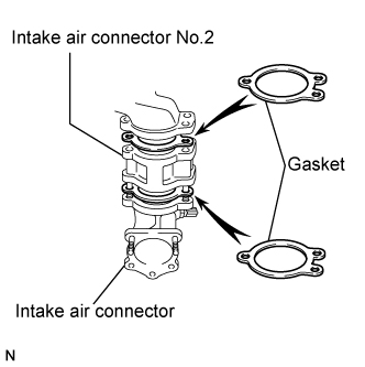
Temporarily install 2 new gaskets and intake air connector No.2 to the intake air connector.
-
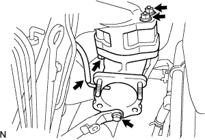
Temporarily tighten the intake air connector assembly with the bolt and 2 nuts.
-
Tighten the manifold stay with the bolt.
-
Tighten the intake air connector with the bolt and 2 nuts.
-
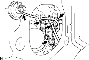
Install the vacuum hose to the intake air connector.
-
-
TEMPORARILY TIGHTEN ELECTRIC EGR CONTROL VALVE ASSEMBLY (w/ EGR Valve)
-
Temporarily tighten the EGR valve assembly with the sensor.
-
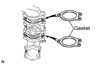
Install 2 new gaskets and the EGR valve to the intake air connector as shown in the illustration.
-
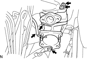
Temporarily tighten the intake air connector with EGR valve assembly to the intake manifold with the bolt and the 2 nuts.
-
Install the vacuum hose to the intake air connector.
-
Temporarily tighten the manifold stay with the bolt.
-
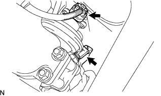
Connect the EGR valve position sensor connector.
-
Connect the intake air temperature sensor connector.
-
-
Install the vacuum regulating valve.
-
Install the vacuum regulating valve with the 2 bolts.
- Torque:
- 20 N*m { 204 kgf*cm, 15 ft.*lbf }
-
Connect the 2 vacuum hoses and the regulating valve connector.
-
-
-
INSTALL EGR PIPE SUB-ASSEMBLY NO.1 (w/ EGR Valve)
-
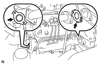
Install the 2 gaskets to the cylinder head and EGR pipe sub-assembly as shown in the illustration.
-
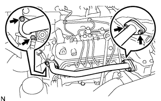
Install the EGR pipe sub-assembly with the 2 bolts and 2 nuts.
- Torque:
- 13 N*m { 133 kgf*cm, 10 ft.*lbf }
-
Tighten the intake air connector with the bolt and the 2 nuts.
- Torque:
- 20 N*m { 204 kgf*cm, 15 ft.*lbf }
-
Tighten the manifold stay.
- Torque:
- 19 N*m { 194 kgf*cm, 14 ft.*lbf }
-
-
REMOVE EGR PIPE SUB-ASSEMBLY NO.1 (w/ EGR Valve)
-
Remove the 3 bolts, the 2 nuts, and the EGR pipe sub-assembly.
-
Remove the 2 gaskets.
-
-
INSTALL ENGINE SERVICE HOLE COVER NO.2
-
Install the engine service hole cover No.2 with the 3 bolts.
- Torque:
- 13 N*m { 133 kgf*cm, 10 ft.*lbf }
-
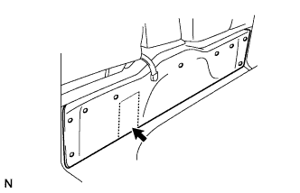
Return the carpet.
-
-
INSTALL DIESEL THROTTLE BODY ASSEMBLY
Note
After removing and installing, or replacing the throttle body, be sure to perform the operation check.
-
Install a new gasket to intake air connector.
-
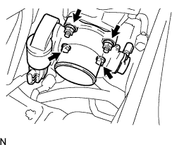
Install the throttle body with the 2 bolts and the 2 nuts.
- Torque:
- 20 N*m { 204 kgf*cm, 15 ft.*lbf }
-
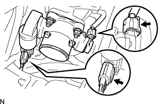
Connect the 2 throttle body connectors.
-
-
INSTALL AIR HOSE NO.4
-
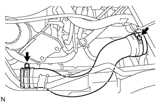
Install the air hose No.4 with the 2 clamps.
- Torque:
- 6.0 N*m { 61 kgf*cm, 53 in.*lbf }
-
-
INSTALL EGR PIPE SUB-ASSEMBLY NO.1 (w/ EGR Valve)
-
Install 2 new gaskets to the cylinder head and the EGR pipe sub-assembly No.1 as shown in the illustration.
-
Install the EGR pipe with the 2 bolts and the 2 nuts.
- Torque:
- 13 N*m { 133 kgf*cm, 10 ft.*lbf }
-
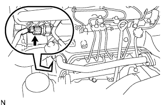
Connect the fuel pressure sensor connector.
-
-
INSTALL OIL RETURN HOSE (w/ Intercooler)
-
INSTALL VANE PUMP OIL RESERVOIR ASSEMBLY
-
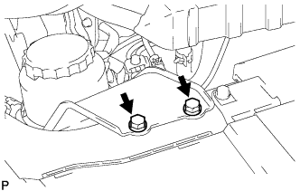
Установите масляный бачок лопастного насоса в сборе и закрепите 2 болтами.
- Torque:
- 8,0 Н*м { 82 кгс*см, 71 фунт-сила-дюйм }
-
-
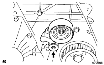
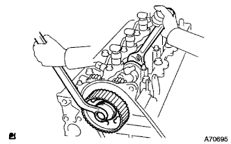
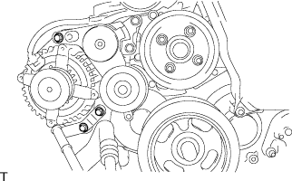
INSTALL TIMING BELT
-
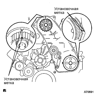
Удостоверьтесь, что установочные метки совмещены, как показано на рисунке.
-
Установите приводной ремень газораспределения на шкив приводного вала насоса, зубчатое колесо распредвала и опорный ролик приводного ремня газораспределения № 1, придерживаясь этой последовательности.
-

Установите натяжитель вертикально на пресс.
Note
-
Не допускайте царапания и деформирования конца толкателя.
-
Запрессуйте толкатель натяжителя.
-
Обеспечьте защиту конца толкателя от повреждений ветошью.
-
-
С помощью пресса медленно запрессуйте толкатель с усилием 981 - 9807 Н (100 - 1000 кгс, 220 - 2205 фунт-силы).
Note
Не прикладывайте к толкателю усилие свыше 981 - 9807 Н (100 - 1000 кгс, 220 - 2205 фунт-силы).
-
Совместите отверстия в толкателе и кожухе. Для сохранения положения установки толкателя пропустите через отверстия шестигранную головку на 1,27 мм.
-
Временно закрепите натяжитель приводного ремня 2 болтами, прижимая опорный ролик к приводному ремню газораспределения.
-
Затяните 2 болта.
- Torque:
- 13 Н*м { 133 кгс*см, 10 фунт-сила-футов }
Note
Равномерно затяните 2 болта и установите натяжитель
-
Выньте из натяжителя торцевой гаечный ключ на 1,5 мм.
-
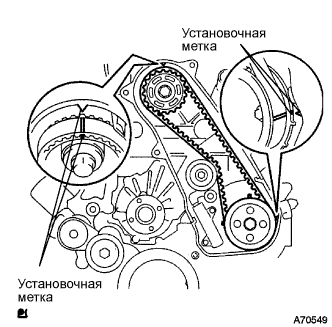
Поверните коленчатый вал по часовой стрелке на два оборота и убедитесь, что установочные метки совмещены, как показано на рисунке.
-
-
INSTALL TIMING BELT COVER NO.1
-
Установите крышку приводного ремня газораспределения № 1 и закрепите ее 6 болтами.
- Torque:
- 6,0 Н*м { 61 кгс*см, 53 фунт-сила-дюйма }
-
Присоедините зажим жгута проводов.
-
-
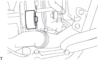
INSTALL FAN PULLEY
-
Install the fan pulley with the 4 bolts.
- Torque:
- 23 N*m { 235 kgf*cm, 17 ft.*lbf }
-
-
INSTALL V-RIBBED BELT TENSIONER ASSEMBLY
-
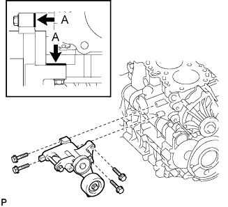
Временно установите натяжитель поликлинового ремня и закрепите его 4 болтами.
Tech Tips
Убедитесь, что натяжитель поликлинового ремня касается блока цилиндров в точках A, показанных на рисунке.
-
Закрепите натяжитель поликлинового ремня 4 болтами.
- Torque:
- 21 Н*м { 214 кгс*см, 15 фунт-сила-футов }
-
-
INSTALL GENERATOR ASSEMBLY
-
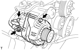
Install the generator assembly with the bolt.
- Torque:
- 62 N*m { 632 kgf*cm, 46 ft.*lbf }
-
Install the generator wire to terminal B with the nut.
- Torque:
- 9.8 N*m { 100 kgf*cm, 7 ft.*lbf }
-
Install the terminal cap.
-
Connect the generator connector.
-
-
INSTALL GENERATOR BRACKET
-
Install the generator bracket with the 2 bolts.
- Torque:
- 36 N*m { 367 kgf*cm, 27 ft.*lbf }
-
-
INSTALL IDLE PULLEY ASSEMBLY (w/ Air Conditioning System)
-
Install the idle No.2 pulley assembly and washer with the bolt.
- Torque:
- 45 N*m { 459 kgf*cm, 33 ft.*lbf }
-
-
INSTALL COMPRESSOR OUTLET ELBOW
-
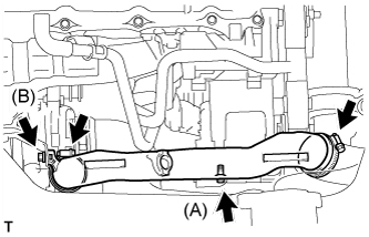
Install the compressor outlet elbow with the 2 bolts and 2 clamps.
- Torque:
- Bolt (A)
- 12 N*m { 122 kgf*cm, 9 ft.*lbf }
- Bolt (B)
- 32 N*m { 326 kgf*cm, 24 ft.*lbf }
-
-
INSTALL AIR CLEANER HOSE ASSEMBLY
-
Install the air cleaner hose assembly with the clamp.
-
-
INSTALL AIR TUBE ASSEMBLY
-
Install the air tube assembly with the 2 clamps and 2 bolts.
-
-
INSTALL COMPRESSOR AND MAGNETIC CLUTCH (w/ Air Conditioning System)
-
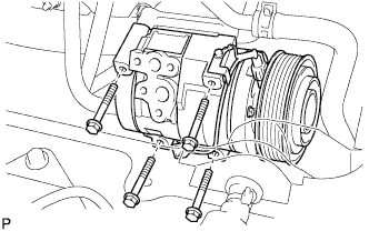
Установите компрессор и электромагнитную муфту и закрепите их 4 болтами.
- Torque:
- 25 Н*м { 255 кгс*см, 18 фунт-сила-футов }
Note
При установке компрессора и электромагнитной муфты затягивайте болты в последовательности, показанной на рисунке.
-
-
INSTALL FAN & GENERATOR V BELT
-
Провернув шкив натяжителя поликлинового ремня по часовой стрелке, установите поликлиновой ремень вентилятора и генератора.
Note
Проверьте правильность посадки поликлинового ремня вентилятора и генератора на каждом шкиве.
-
Проверьте метку индикатора натяжителя поликлинового ремня (см. стр. Click here).
-
-
INSTALL FENDER APRON MUDGUARD SEAL RH
-
INSTALL ENGINE SERVICE HOLE SUB COVER SUB-ASSEMBLY
-
Установите вспомогательную крышку технологического отверстия двигателя и закрепите ее 5 болтами.
- Torque:
- 13 Н*м { 133 кгс*см, 10 фунт-сила-футов }
-
-
CONNECT BATTERY NEGATIVE CABLE
-
INSTALL FRONT SEAT ASSEMBLY RH (for Hi-back Seat Type)
Tech Tips
Perform the same procedure as RH side on the LH side.
-
INSTALL FRONT SEAT ASSEMBLY RH (for Low-back Seat Type)
Tech Tips
Perform the same procedure as RH side on the LH side.
-
INSTALL FRONT DOOR SCUFF PLATE RH
-
ADD ENGINE COOLANT
-
Надежно затяните сливные пробки и залейте в расширительный бачок радиатора охлаждающую жидкость до верха горловины.
-
Ослабьте прокачной штуцер корпуса отводящего патрубка.
-
После удаления воздуха и слива охлаждающей жидкости надежно затяните прокачной штуцер.
-
Долейте охлаждающую жидкость в расширительный бачок системы охлаждения до отметки B и установите пробку радиатора.
Объем охлаждающей жидкости Условие Объем Для моделей с задним подогревателем 17,0 литра (18,0 кварты США, 15,0 английской кварты) Для моделей без заднего подогревателя 15,0 литра (15,9 кварты США, 13,2 английской кварты) -
Прогрейте двигатель.
-
После охлаждения двигателя убедитесь, что уровень охлаждающей жидкости находится между отметками "LOW" и "FULL".
-
-
CHECK FOR ENGINE COOLANT LEAKAGE
CAUTION:
Не снимайте пробку радиатора, пока двигатель и радиатор не остынут. Выброс горячей охлаждающей жидкости и пара под давлением может стать причиной серьезных ожогов.
-
Заполните радиатор охлаждающей жидкостью и подсоедините к радиатору приспособление для опрессовки системы охлаждения и проверки пробки радиатора.
-
Прогрейте двигатель.
-
С помощью приспособления для опрессовки системы охлаждения и проверки пробки радиатора увеличьте давление в радиаторе до 137 кПа (1,4 кгс/см2, 19,9 фунтов на кв. дюйм) и убедитесь, что давление не падает.
Tech Tips
Если давление снижается, проверьте на наличие утечек шланги, радиатор и насос системы охлаждения. При отсутствии внешних утечек проверьте сердцевину отопителя, блок цилиндров и головку блока цилиндров.
-
-
INSTALL ENGINE UNDER COVER NO.1